Table of Contents
Advertisement
Quick Links
Advertisement
Table of Contents

Related Manuals for Amphenol 125GMT15


Summary of Contents for Amphenol 125GMT15
- Page 1 125GMT10/125GMT15 Installation Guide...
- Page 2 Amphenol Network Solutions assumes no liability from the application or use of these products. Amphenol Network Solutions does not convey any license under its patent rights nor the patent rights of others. This document and the products described herein are subject to change without notice.
-
Page 3: Table Of Contents
Fig. 1-2: 125GMT15 rear view ........................6 Fig. 1-3: 125GMT10-C front view ......................... 7 Fig. 1-4: 125GMT10-C rear view ......................... 7 Fig. 2-1: Installing mounting brackets ......................10 125GMT Amphenol Network Solutions All rights reserved. 3.18.20 150566 509.926.6000 — amphenol-ns.com.com... - Page 4 Fig. 3-8: 125GMT10 and 125GMT15 Bottom view ..................24 Fig. 3-9: 125GMT10-C and 125GMT15-C Bottom view ................24 Fig. 3-10: 125GMT10-C and 125GMT15-C with optional Tie Bar ............... 24 125GMT Amphenol Network Solutions All rights reserved. 3.18.20 150566 509.926.6000 — amphenol-ns.com.com...
-
Page 5: Section One: Overview
WARNING! Indicates a hazardous situation, which could result in death or serious injury. Amphenol Network Solutions assumes no liability from the application or use of these products. Amphenol Network Solutions does not convey a license under its patent rights, nor the patent rights of others. This document and the products described herein are subject to change without notice. -
Page 6: 125Gmt Configurations
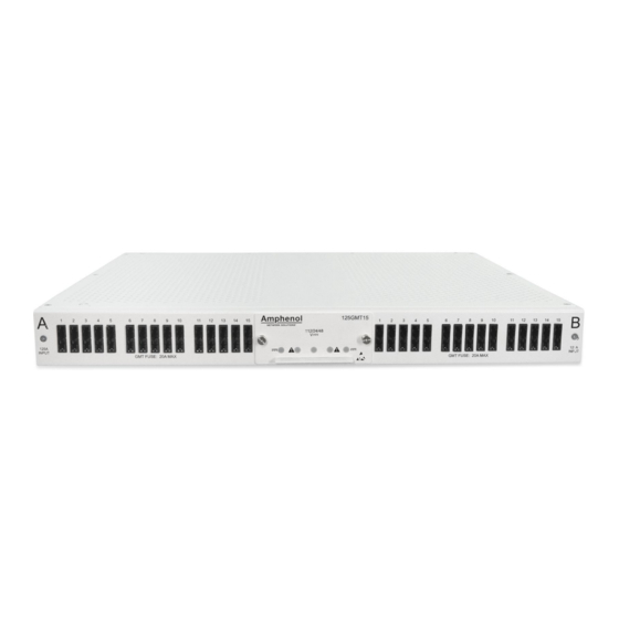
(Connectors purchased separately) 1.3 125GMT Overview The Amphenol Network Solutions 125GMT family of 1RU, dual-feed 125A per feed, power distribution panels provide high-capacity, ±48V, ±24V, and ±12V power protection for secondary power distribution to data and communications equipment. The Amphenol Network Solutions 125GMT family panels are also ideal for primary distribution in small central offices and at remote sites. -
Page 7: Fig. 1-3: 125Gmt10-C Front View
20 or 30 GMT fuses, respectively. The panel is UL rated using 20A GMT fuses with a maximum continuous output load of 14A. GMT fuses are sold separately. See amphenol-ns.com to order GMT fuses. Sides A and B are electrically isolated including the alarm card, which contains power and GMT fuse status relays with dry, Form-C contacts. -
Page 8: Specifications
17" (432 mm) without brackets 19” and 23” brackets included with panel Tie bar not included with panel Cable-end connectors not included with panel Compliance: Specifications: Listed NEBS Level 3 125GMT Amphenol Network Solutions All rights reserved. 3.18.20 150566 509.926.6000 — amphenol-ns.com.com... -
Page 9: Section Two: Installation
Amphenol Network Solutions Quality at quality@amphenol-ns.com or call 1-509- 926-6000. Amphenol Network Solutions is not liable for transit damage. If the product is damaged, please report it to the carrier and contact Amphenol Network Solutions Quality. -
Page 10: Mounting Brackets
3. Use included hardware in accessory kit to install tie bar. Standard tie bar is available as an accessory for connectorized panels. 4. Tighten screws to 8 in/lb. (.9 N•m). Fig. 2-2: Installing optional tie bar 125GMT Amphenol Network Solutions All rights reserved. 3.18.20 150566 509.926.6000 — amphenol-ns.com.com... -
Page 11: Rack Mounting
2-3. Mount the panel as high as possible on the rack. Use a seismic rack for best rigidity. 6. Tighten screws to 35 in/lb. (3.9 N•m). Fig. 2-3: Installing panel in rack 125GMT Amphenol Network Solutions All rights reserved. 3.18.20 150566 509.926.6000 — amphenol-ns.com.com... -
Page 12: Grounding
-20 bolts, split washers and flat washers provided, as shown in Fig. 2-4. 9. Tighten the bolt to 50 in/lb. (5.6 N•m), max. Fig. 2-4: Grounding lug connection 125GMT Amphenol Network Solutions All rights reserved. 3.18.20 150566 509.926.6000 — amphenol-ns.com.com... -
Page 13: Input Wiring
14. If required, lightly coat antioxidant on lugs and input BATT and RTN terminals and then connect lugs to input terminals, as shown in Fig. 2-5. 15. Tighten nut to 50 in/lb. (5.6 N•m), max. Fig. 2-5: Input lugs 125GMT Amphenol Network Solutions All rights reserved. 3.18.20 150566 509.926.6000 — amphenol-ns.com.com... -
Page 14: Remove Alarm Cover
Expect continuity (0Ω) between terminals C and NO 19. With no output wires connected or with the output loads (devices fed by this panel) disabled, install fuses into the fuse positions. 125GMT Amphenol Network Solutions All rights reserved. 3.18.20 150566 509.926.6000 — amphenol-ns.com.com... -
Page 15: Installing Fuses
As an alternate to wire wrap, TE Connectivity insulation displacement connector, part number 3-640428-3, can be used to connect to the alarm terminals. Alarm terminals Fig. 2-8: 125GMT15-C Alarm Terminals 125GMT Amphenol Network Solutions All rights reserved. 3.18.20 150566 509.926.6000 — amphenol-ns.com.com... -
Page 16: Output Wiring (Terminal Block Versions)
33. If applicable, check voltage and polarity at loads. 34. Record circuit assignments in accordance with operating company procedures and guidelines. 35. Enable equipment loads one at a time to verify proper operation of loads. 125GMT Amphenol Network Solutions All rights reserved. 3.18.20 150566 509.926.6000 — amphenol-ns.com.com... -
Page 17: Output Wiring (Connectorized Versions)
2 Locator Fins: Battery 1 Locator Fin: Return Fig. 2-11: Connector front view 38. Insert retainer into plug housing as shown in Fig. 2-12. Fig. 2-12: Insert retainer 125GMT Amphenol Network Solutions All rights reserved. 3.18.20 150566 509.926.6000 — amphenol-ns.com.com... -
Page 18: Fig. 2-13: Insert Connector
41. If applicable, check voltage and polarity at loads. 42. Record circuit assignments in accordance with operating company procedures and guidelines. 43. Enable equipment loads one at a time to verify proper operation of loads. 125GMT Amphenol Network Solutions All rights reserved. 3.18.20 150566 509.926.6000 — amphenol-ns.com.com... -
Page 19: Install Rear Cover
WARNING! The rear cover protects the rear of the panel while energized. Not installing the rear cover may create an electrical hazard. 44. Install rear plastic cover using provided hardware, as shown in fig. 2-14. Fig. 2-14: Rear Cover 125GMT Amphenol Network Solutions All rights reserved. 3.18.20 150566 509.926.6000 — amphenol-ns.com.com... -
Page 20: Tie Bar
The following tables list optional and replacement items for the panel. For wire sizing and labeling, please refer to Wire Sizing & Label Convention (Amphenol Network Solutions Part No. 117995) included with your panel. Order parts and accessories online at amphenol-ns.com. -
Page 21: Ordering Information
100151 1/2A 004001 3/4A 004008 100991 1-1/3A 004006 1-1/2A 004011 004002 2-1/2A 130783 004012 3-1/2A 130782 004013 004014 7-1/2A 004010 004015 102287 102288 127240 20A with cover 131340 125GMT Amphenol Network Solutions All rights reserved. 3.18.20 150566 509.926.6000 — amphenol-ns.com.com... -
Page 22: Lug Reference Guide
Burndy YA6CLNT6* YA8CLNT6* YAE14N-43BOX YAE18N-21BOX *Narrow tongue lug Ground Cables: 2 Hole " on " Centers T&B 54208 54207 54206 Panduit LCD1-14A-E LCD2-14A-Q LCD4-14A-L Burndy YA1CL-2TC14 YA2CL-2TC14 YA4CL-2TC14 125GMT Amphenol Network Solutions All rights reserved. 3.18.20 150566 509.926.6000 — amphenol-ns.com.com... -
Page 23: Section Three: Drawings
Section Three: Drawings 3.1 125GMT Drawings Fig. 3-1: 125GMT10 and 125GMT10-C Front view Fig. 3-2: 125GMT15 and 125GMT15-C Front view Fig. 3-3: 125GMT10, 125GMT15, 125GMT10-C and 125GMT15-C Side view 125GMT Amphenol Network Solutions All rights reserved. 3.18.20 150566 509.926.6000 — amphenol-ns.com.com... -
Page 24: Fig. 3-4: 125Gmt10 Rear View
Fig. 3-4: 125GMT10 Rear view Fig. 3-5: 125GMT15 Rear view Fig. 3-6: 125GMT10-C Rear view Fig. 3-7: 125GMT15-C Rear view 125GMT Amphenol Network Solutions All rights reserved. 3.18.20 150566 509.926.6000 — amphenol-ns.com.com... -
Page 25: Fig. 3-8: 125Gmt10 And 125Gmt15 Bottom View
Fig. 3-8: 125GMT10 and 125GMT15 Bottom view Fig. 3-9: 125GMT10-C and 125GMT15-C Bottom view 125GMT Amphenol Network Solutions All rights reserved. 3.18.20 150566 509.926.6000 — amphenol-ns.com.com... -
Page 26: Fig. 3-10: 125Gmt10-C And 125Gmt15-C With Optional Tie Bar
Fig. 3-10: 125GMT10-C and 125GMT15-C with optional Tie Bar 125GMT Amphenol Network Solutions All rights reserved. 3.18.20 150566 509.926.6000 — amphenol-ns.com.com...
Need help?
Do you have a question about the 125GMT15 and is the answer not in the manual?
Questions and answers