Table of Contents
Advertisement
Quick Links
Advertisement
Table of Contents

Related Manuals for Amphenol T009-5030 Series


Summary of Contents for Amphenol T009-5030 Series
- Page 1 100A Dual-Feed Breaker Panel T009-5030XXXXXXX Installation Guide...
- Page 2 Amphenol Network Solutions assumes no liability from the application or use of these products. Amphenol Network Solutions does not convey any license under its patent rights nor the patent rights of others. This document and the products described herein are subject to change without notice.
-
Page 3: Table Of Contents
Figure 6 – Alarm Indicators ........................6 Figure 7 – Alarm Terminals ........................6 Figure 8 – Designation Label ........................7 Figure 9 – Tab Release ........................... 8 100A Dual-Feed Amphenol Network Solutions All rights reserved. 12.18.19 139688-3 Breaker Panel 509.926.6000 – amphenol-ns.com... -
Page 4: Overview
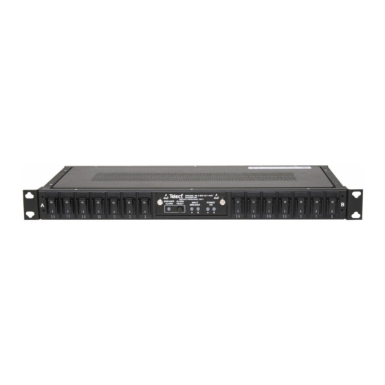
1.1 Overview Front The Amphenol Network Solutions dual- feed configurable breaker panel provides circuit breaker power protection for a variety of telecommunications equipment. The panel includes seven circuit breakers per side (configurable from 1A to 20A) Rear for a total maximum continuous output load Figure 1 –... - Page 5 42W per side at 4800W (100A x 48V) per side Percentage of full load heat dissipation at Less than 1% of total load wattage nominal voltage 100A Dual-Feed Amphenol Network Solutions All rights reserved. 12.18.19 139688-3 Breaker Panel 509.926.6000 – amphenol-ns.com...
-
Page 6: Inspection
Immediately report any shipping damage, defects or missing parts to Amphenol Network Solutions at 509-926-6000. Keep all documentation that comes with your shipment. Amphenol Network Solutions is not liable for shipping damage. If the product is damaged, notify the carrier and call Amphenol Network Solutions at 509-926-6000 for further recourse. -
Page 7: Installation
ALERT! Only use components and crimping tools approved by agencies or certifying bodies recognized in your country or region such as Underwriter’s Laboratories (UL), TUV, etc. 100A Dual-Feed Amphenol Network Solutions All rights reserved. 12.18.19 139688-3 Breaker Panel 509.926.6000 – amphenol-ns.com... -
Page 8: Figure 4 - Ground Lug Connection
4. Use a coarse, nonmetallic cleaning pad to clean terminals and stud(s). 5. Amphenol Network Solutions recommends that you lightly coat antioxidant on the lug, grounding terminal and surrounding contacting surface.Connect the lug to the stud using an M5 washer and nut from the terminal, as shown in Figure 4. -
Page 9: Figure 6 - Alarm Indicators
10 AWG.) • If using bare wire, strip off ⅝ in. (~1.5 cm) of insulation. (Stranded wires should be tinned.) 100A Dual-Feed Amphenol Network Solutions All rights reserved. 12.18.19 139688-3 Breaker Panel 509.926.6000 – amphenol-ns.com... -
Page 10: Figure 8 - Designation Label
19. If covers are installed, remove the covers over the output and alarm connectors. 20. Amphenol Network Solutions recommends that you lightly coat antioxidant on lugs and output BATTERY and RETURN terminals before connecting lugs/wires to outputs. (NEC specifies only one lug and load for each output terminal.) Tighten the screws to 9 in.-lb (1.01 N•m). -
Page 11: Replacing Output Circuit Breakers
ALERT! The LINE side connection of the breaker has live VDC. Do not allow contact of the connector (or tools holding the connector) to grounded ironwork or panel chassis. 100A Dual-Feed Amphenol Network Solutions All rights reserved. 12.18.19 139688-3 Breaker Panel... - Page 12 15. If the input power was turned off, restore input power and turn on breakers one at a time. 16. When you turn the new breaker on, check the output terminal for correct polarity. This procedure is complete. 100A Dual-Feed Amphenol Network Solutions All rights reserved. 12.18.19 139688-3 Breaker Panel 509.926.6000 – amphenol-ns.com...
-
Page 13: Accessories
1.5 Accessories The following table lists optional and replacement items for the panel. For compression lugs, please refer to the Wiring Sizing & Label Convention Chart (Amphenol Network Solutions Part No. 117995) included with your panel. Item Description Part Number Alarm Card Power &... -
Page 14: Led & Alarm Summary
C to NC opens b. C to NO closes Pressing ALARM RESET turns off the BREAKER ALARM LED and de-energizes the FUSE ALARM relay. 100A Dual-Feed Amphenol Network Solutions All rights reserved. 12.18.19 139688-3 Breaker Panel 509.926.6000 – amphenol-ns.com... -
Page 15: Schematic Drawing
1.7 Schematic Drawing (Not Used) (Not Used) (Shown in alarm state) 100A Dual-Feed Amphenol Network Solutions All rights reserved. 12.18.19 139688-3 Breaker Panel 509.926.6000 – amphenol-ns.com... -
Page 16: Assembly Drawing
Amphenol Network Solutions assumes no liability from the application or use of these products. Neither does Amphenol Network Solutions convey any license under its patent rights or the patent rights of others. This document and the products described herein are subject to change without notice.
Need help?
Do you have a question about the T009-5030 Series and is the answer not in the manual?
Questions and answers