Table of Contents
Advertisement
Advertisement
Chapters
Table of Contents

Related Manuals for Baseline 12-0341


Summary of Contents for Baseline 12-0341
- Page 1 Push / Pull Dynamometers 12-0340 12-0341 12-0342 12-0343 User’s Guide...
-
Page 2: Table Of Contents
For additional information or answers to your questions, please do not hesitate to contact us. Our technical support and engineering teams are eager to assist you. Before use, each person who is to use a Baseline dynamometer should be fully trained in appropriate operation and safety procedures. -
Page 3: Safety
User’s Guide Baseline® Push / Pull Dynamometers 1 SAFETY Caution! Note the dynamometer’s capacity before use and ensure that the capacity is not exceeded. Producing a force greater than 200% of the dynamometer’s capacity can damage the internal load cell. An overload can occur whether the dynamometer is powered on or off. -
Page 4: Power
User’s Guide Baseline® Push / Pull Dynamometers 2 POWER Caution! Do not use AC adapters other than supplied or instrument damage may occur. The dynamometer is powered either by an 8.4V rechargeable battery or by an AC adapter (input jack is located in the left side of the housing). -
Page 5: Mechanical Setup
User’s Guide Baseline® Push / Pull Dynamometers 3 MECHANICAL SETUP 3.1 Loading shaft orientation In order to accommodate a variety of testing requirements, the orientation of the loading shaft may be oriented in either of the two positions shown below. To change the loading shaft orientation, loosen the two captive screws on the back side of the housing, separate the two housing halves, rotate one half 180 degrees, and reassemble. -
Page 6: Home Screen And Controls
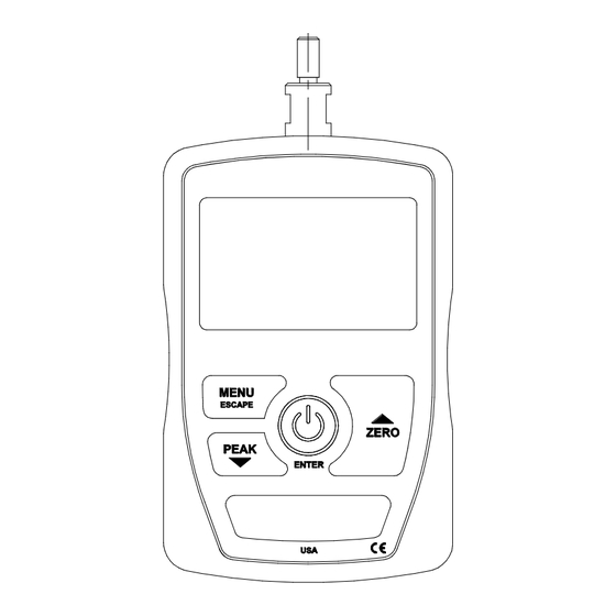
User’s Guide Baseline® Push / Pull Dynamometers 4 HOME SCREEN AND CONTROLS 4.1 Home Screen Name Description Primary reading The current displayed force reading. See Operating Modes section for details. Units The current unit of measurement. Abbreviations are as follows: lbF –... -
Page 7: Operating Modes
User’s Guide Baseline® Push / Pull Dynamometers 4.3 Menu navigation basics Most of the dynamometer’s various functions and parameters are configured through the main menu. To access the menu press MENU. Use the UP and DOWN keys to scroll through the items. The current selection is denoted with clear text over a dark background. -
Page 8: Digital Filters
User’s Guide Baseline® Push / Pull Dynamometers 7 DIGITAL FILTERS Digital filters are provided to help smooth out the readings in situations where there is mechanical interference in the work area or test sample. These filters utilize the moving average technique in which consecutive readings are pushed through a buffer and the displayed reading is the average of the buffer contents. - Page 9 User’s Guide Baseline® Push / Pull Dynamometers CALIBRATION Enter # cal points (1 to 10) Compression: Tension: The dynamometer can be calibrated at up to 10 points in each direction. Enter the number of calibration points for each direction (compression and tension). At least one point must be selected for each direction.
- Page 10 User’s Guide Baseline® Push / Pull Dynamometers CALIBRATION CALIBRATION OFFSET OFFSET Sensor Passed Sensor Failed Analog Passed Analog Failed If failed: 6. The following screen appears after the offsets have been calculated: CALIBRATION COMPRESSION Attach necessary weight fixtures, then press ENTER Attach weight fixtures (brackets, hooks, etc), as required.
- Page 11 User’s Guide Baseline® Push / Pull Dynamometers 10. The display appears as follows: CALIBRATION COMPRESSION Apply load 1 OF 5 Enter load: 20.000 lbF Press ENTER Use the UP and DOWN keys to adjust the load value as required. The load values default to even increments, as indicated by the previously entered number of data points (even increments are recommended for best results).
- Page 12 User’s Guide Baseline® Push / Pull Dynamometers 14. Any errors are reported by the following screens: CALIBRATION Units must be kgF Please try again Press ENTER Displayed at the start of calibration if a disallowed unit is selected. CALIBRATION Load not stable Please try again Ensure that the load is not swinging, oscillating, or vibrating in any manner.
-
Page 13: Other Settings
User’s Guide Baseline® Push / Pull Dynamometers 9 OTHER SETTINGS 9.1 Automatic Shutoff The dynamometer may be configured to automatically power off following a period of inactivity while on battery power. Inactivity is defined as the absence of any key presses or load changes of 100 counts or less. -
Page 14: Lcd Contrast
User’s Guide Baseline® Push / Pull Dynamometers LCD CONTRAST Set Contrast Press ENTER to modify the contrast. Select a value from 0 to 25, 25 producing the most contrast. 9.4 Initial Mode This section is used to configure the initial mode upon powering on the dynamometer. To access this parameter, select Initial Mode from the menu. -
Page 15: Specifications
Battery life: Backlight off: up to 24 hours of continuous use 200% of full scale (display shows “OVER” at 110% and above) Safe overload: 12-0340 – 12-0341: 0.7 lb [0.33 kg] Weight: 12-0342 – 12-0343: 0.9 lb [0.41 kg] Environmental 40 - 100°F, max. - Page 16 User’s Guide Baseline® Push / Pull Dynamometers 10.4 Dimensions IN [MM]...
- Page 17 User’s Guide Baseline® Push / Pull Dynamometers NOTES:...
-
Page 18: Model Lbf Kgf N
User’s Guide Baseline® Push / Pull Dynamometers The Baseline® electronic push-pull dynamometer uses state-of-the-art “load-cell” technology to assure the highest standards of accuracy, repeatability and reliability. The unit is available in four measurement ranges and comes complete with 3 push pads, 1 pull hook, 1 snap hook and a padded carrying case. Optional single and dual grip handles available.
Need help?
Do you have a question about the 12-0341 and is the answer not in the manual?
Questions and answers