Table of Contents
Advertisement
Advertisement
Table of Contents

Related Manuals for HP A5120-48G SI


Summarization of Contents
Preparing for Installation
Safety Recommendations
General safety guidelines for installation and operation.
Installation Site Requirements
Conditions for the installation environment, including temperature, humidity, and dust.
Installation Tools
Lists user-supplied tools required for installation.
Rack-Mounting Requirements
Requirements for mounting the switch in a rack, including rack stability and heat dissipation.
Installing the Switch
Rack-Mounting the A5120 El Switch in a 19-inch Rack
Detailed steps for mounting the A5120 El switch in a 19-inch rack.
Mounting Brackets
Information about mounting brackets used for switch installation.
Rack-Mounting Using Only Front Mounting Brackets
Procedure for rack mounting using only front brackets.
Rack-Mounting Using Front Mounting Brackets and a Rack Shelf
Procedure for rack mounting with front brackets and a rack shelf.
Rack-Mounting by Using Front and Rear Mounting Brackets
Procedure for rack mounting using front and rear brackets.
Mounting the Switch on a Workbench
Instructions for mounting the switch on a workbench.
Grounding the Switch
Grounding to a Grounding Strip
Connects the switch to a grounding strip for electrical safety.
Grounding to a Buried Grounding Conductor
Connects the switch to an earth ground using a buried conductor.
Grounding Through the AC Power Cord
Grounds the switch using the equipment's AC power cord.
Connecting the Power Cord
Connecting the AC Power Cord
Step-by-step guide to connect the AC power cord to the switch.
Connecting the Switch to a +12 VDC Output RPS
Connects the switch to a +12 VDC Redundant Power Supply (RPS).
Connecting the Switch to a −52 to −55 VDC Output RPS
Connects the switch to a -52 to -55 VDC Redundant Power Supply (RPS).
Installing/Removing an Interface Card (A5120 El Switches Only)
Installing an Interface Card
Procedure for installing an interface card into the switch.
Removing an Interface Card
Procedure for removing an interface card from the switch.
Installing/Removing a Dedicated CX4/SFP+ Cable
Instructions for connecting and disconnecting CX4/SFP+ cables.
Verifying the Installation
Verification Before Power-On
Checks that all installation steps are completed correctly before powering on.
Accessing the Switch for the First Time
Setting Up the Configuration Environment
Steps to prepare a terminal for switch configuration.
Connecting the Console Cable
Describes the console cable and how to connect it.
Connection Procedure
Steps for connecting a PC or terminal to the switch via console port.
Setting Terminal Parameters
Details required terminal settings (baud rate, parity, etc.) for console access.
Powering On the Switch
Verification Before Power-On
Checks that all installation steps are completed correctly before powering on.
Power-On Sequence
Describes the sequence of events when the switch powers on.
Changing the Startup Mode
Changing the Startup Mode
How to switch between fast startup and full startup modes.
Setting Up an IRF Fabric
Planning IRF Fabric Setup
Planning considerations for setting up an IRF fabric.
Identifying the Master Switch and Planning IRF Member IDs
Steps for identifying the master and assigning member IDs in an IRF fabric.
Planning IRF Topology and Connections
Planning the network topology and physical connections for IRF.
Accessing the IRF Fabric to Verify the Configuration
Verifying the IRF fabric functionality and configuration.
Identifying Physical IRF Ports on the Member Switches
How to identify the specific ports used for IRF connections.
Planning the Cabling Scheme
Planning the physical cabling for IRF connections.
Configuring Basic IRF Settings
Basic configuration steps for establishing an IRF fabric.
Connecting the Physical IRF Ports
Guide for physically connecting the IRF member switches.
Maintenance and Troubleshooting
Password Loss
Procedures for recovering lost console login or Boot ROM passwords.
Boot ROM Password Loss
Instructions for recovering from lost Boot ROM passwords.
Power Supply Failure
Troubleshooting steps for power supply issues.
Fan Failure (A5120 El Switches Only)
Diagnosing and addressing fan failure issues.
Console Terminal Problems
Troubleshooting issues with console terminal display or connectivity.
Support and Other Resources
Contacting HP
Information on how to contact HP for support.
Subscription Service
Information about registering products and receiving updates.
Related Information
Links to additional documents and resources.
Conventions
Command Conventions
Explains conventions used for command-line interface syntax.
GUI Conventions
Explains conventions used for graphical user interface elements.
Symbols
Defines symbols like WARNING, CAUTION, IMPORTANT, NOTE, TIP.
Appendix A Technical Specifications
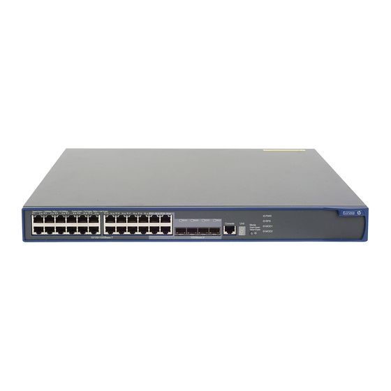
Panel Views
Diagrams showing front and rear panel layouts of various switch models.
Chassis Dimensions and Weights
Table detailing physical dimensions and weights of different switch models.
Ports and Interface Card Slots
Table listing available ports and interface card slots for each switch model.
Power Specifications
Details on power input types, voltage, and consumption for switches.
Appendix B FRUs and Compatibility Matrixes
Interface Cards (A5120 El Switches Only)
Lists available interface cards for A5120 El switches and their compatibility.
SFP/SFP+/XFP Transceiver Modules and SFP+/CX4 Cables (A5120 El Switches Only)
Information on transceiver modules and cables for A5120 El switches.
SFP Transceiver Modules and SFP Stacking Kit (Only for the A5120 SI Switches)
Details SFP modules and stacking kits for A5120 SI switches.
Appendix C Ports and LEDs
Ports
Describes console, Ethernet, and SFP ports on the switches.
Combo Interface (Only Available on the A5120 El Switches)
Explains combo ports on A5120 El switches.
LEDs (for the A5120 El Switches)
Lists and describes LEDs for A5120 El switches.
LEDs (for the A5120 SI Switches)
Lists and describes LEDs specific to A5120 SI switches.
Need help?
Do you have a question about the A5120-48G SI and is the answer not in the manual?
Questions and answers