Table of Contents
Advertisement
Use
CE1N3072en
2014-04-04
RDJ10RF
Wireless room temperature
controller with 24-hour time
switch and LCD
Programmable, for heating systems
· Operating modes: Automatic, Comfort, Energy Saving, and Frost Protection
· LCD-Display 50 x 45 (W x H)
· RDJ10RF transmitter, battery-powered
· RCR10/433 receiver, mains powered
· Communication of the set is bonded ex factory
The RDJ10RF is used to control the room temperature in heating or cooling systems.
Typical applications include:
· Homes
· Residential buildings
· Schools
· Offices
The controller can be used together with the following equipment:
· Thermal valves or zone valves
· Combi boilers
· Gas or oil burners
· Fans
· Pumps
RCR10/433
RDJ10RF/SET
Building Technologies
3
072
Advertisement
Table of Contents

Related Manuals for Siemens RCR10/433


Summarization of Contents
Functions
Operating modes
Details on Automatic, Comfort, Energy Saving, and Frost Protection modes, including display indicators.
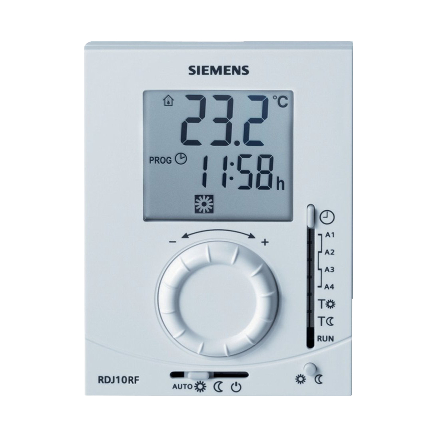
Display
Describes the digital display of actual room temperature and comfort setpoint, and heating output indicator.
Backup
Explains retention of settings during battery exchange and time reset.
Mechanical Design
RCR10/433 Receiver Design
Describes the RCR10/433 receiver's plastic housing, LEDs, and buttons.
RDJ10RF Controller Design
Describes the RDJ10RF controller's plastic housing and accessible rear buttons.
Override Functionality
Override Operation
Explains temporary overwriting of active values based on connection status.
RF LED Indicators
Details RF LED states during power up, learning, and signal reception.
Relay LED Indicators
Details Relay LED states during output transitions and OFF status.
Mounting, Installation and Commissioning
Mounting Location and Height
Guidance on optimal room location, mounting height (1.5m), and conduit box fitting.
Installation and Commissioning
Steps for fixing baseplate, connecting receiver, mounting controller, and commissioning.
Maintenance
Battery Replacement
Information on replacing batteries when the battery symbol appears.
Reset Procedure
Instructions for resetting the controller and receiver using specific button combinations.
Connection Diagram
Wiring Diagram
Illustrates the electrical connections for the system.
Application Examples
Shows typical system configurations for boilers, burners, and pumps.
Dimensions
Controller Dimensions
Provides overall dimensions for the RDJ10RF controller unit.
Mounting Plate Dimensions
Details the dimensions and screw hole layout for the mounting plate.
Controller with Stand Dimensions
Shows dimensions of the controller when using the fold-out stand.
Need help?
Do you have a question about the RCR10/433 and is the answer not in the manual?
Questions and answers