Table of Contents
Advertisement
Quick Links
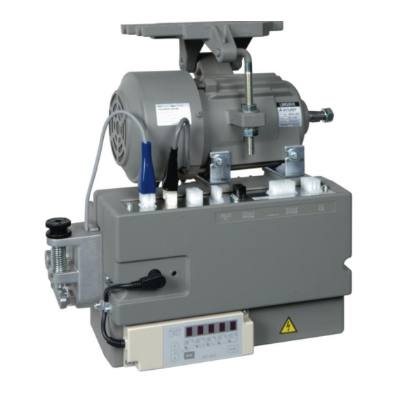
Mitsubishi Limiservo X G series
TECHNICAL INFORMATION MANUAL
Thank you for purchasing this product.
Please read this manual thoroughly before use to ensure safe and proper use.
Please read the instruction manual for the machine head together with this manual.
Save this manual for future reference.
E723D700-C(201407)
Motor
XL-G554-10(Y), XL-G554-20(Y),
XL-G754-20(Y)
Control box XC-GMFY
Induction type AC servo motor
and control box with automatic
needle positioner
Advertisement
Table of Contents

Related Manuals for Mitsubishi Limiservo XL-G554-20Y


Summary of Contents for Mitsubishi Limiservo XL-G554-20Y
- Page 1 Mitsubishi Limiservo X G series TECHNICAL INFORMATION MANUAL Motor XL-G554-10(Y), XL-G554-20(Y), XL-G754-20(Y) Control box XC-GMFY Induction type AC servo motor and control box with automatic needle positioner Thank you for purchasing this product. Please read this manual thoroughly before use to ensure safe and proper use.
-
Page 2: Table Of Contents
5. Installation of the protective cover ············································································································ 6 6. Installation of the position detector ··········································································································· 7 7. Connection of the Mitsubishi sewing machine and control box ······································································· 7 6 Wire and Grounding ······················································································································· 8 1. Insertion of the power connector ·············································································································· 8 2. -
Page 3: Safety Instructions
2 Safety Instructions 1. To ensure safe use *Always observe the following items to ensure safe use of the industrial sewing machine drive unit (motor and control box). 1.1 Before starting Read all instruction manuals thoroughly before starting use of this drive unit, and follow the technical manuals. Also read the instruction manuals for the installed sewing machine. -
Page 4: Points Of Caution
3 Points of Caution Caution 1. Please remove your foot from the pedal when turning the power ON. 2. Always turn the power OFF when leaving the machine. 3. Do not inspect the control circuit with a tester. 4. Always turn the power switch OFF before tilting the sewing machine, replace the needle or threading the needle. 5. -
Page 5: Names Of Each Part
4 Names of Each Part Detector connector Protective cap (Remove the cap when using.) Option A connector Encoder connector Presser foot Option B connector connector 1. Front side of control box Sewing machine connector Lever connector Connector indication nameplate Front cover fixing screw High-voltage warning plate XC-G10-S control switch panel installation screw hole Lever Unit... -
Page 6: Installation
(**) Refer to page 20 for the pulley diameter to be used when using the Mitsubishi thread trimming sewing machine. -
Page 7: Installation Of The Protective Cover
5. Installation of the protective cover (with belt slip off prevention part) The protective cover is enclosed with the motor as an accessory. 1. Install the protective cover A onto the motor. 2. Install the pulley and attach the belt. (Refer to "3. Installing the pulley"... -
Page 8: Installation Of The Position Detector
Control box 7. Connection of the Mitsubishi sewing machine and control box. Wire the units as shown below. Align the connector shape and direction, and securely insert it. [View of control box from cover side]... -
Page 9: Wire And Grounding
6 Wire and Grounding 1. Insertion of the power connector Confirm the connector form and insertion direction when inserting the power connector into the control box and insert completely. Power connector (6-Pole) Right side of control box Back side of control box Power connector 3-phase power 2. -
Page 10: Confirmation
XC-GMFY-10-05 : 100 to 120V (3) Are the connectors inserted correctly? Insertion of the power connector on page 8. -Power connector from push-button switch Connection of the Mitsubishi sewing machine -Motor connector -Motor encoder connector and control box on page 7. -
Page 11: Adjustments
(The cross-recessed screw A does not need to be loosened at this time.) (two screws) -Always replace the cover after adjustment. Caution Refer to the sewing machine instruction manual when adjusting for use with the Mitsubishi sewing machine. Factory setting UP position detector disc (black)(inner) position... -
Page 12: Adjustment Of Operation Speed
3. Adjustment of operation speed Adjustment of Factory setting Reference each speed (speed) “To change the maximum speed” Maximum speed Page25 4000 Low speed Thread trimming speed Start tack speed 1700 End tack speed 1700 Slow start speed Adjust between the low speed [L] and high speed [H] using Operation speed the [C] and [D] keys on the control switch panel. -
Page 13: Changing The Solenoid Voltage And Output Voltage
9 Changing the solenoid voltage and output voltage 1. To change solenoid voltage DC24V/DC30V Control box side To change solenoid voltage from 24V to 30V (1) Remove the front cover from the control box. (2) Reconnect the connector inserted in JP1 on the PCB to the 30V side. -
Page 14: Operation Of The Control Switch Panel Keys
* The state set with each program mode can be returned to the original settings (factory settings). Program mode [1] Simple setting mode for Mitsubishi thread trimming sewing machine. Program mode [2] Simple setting mode for chain stitch sewing machine. -
Page 15: Selection Of Each Program Mode From The Normal Mode
(2) Selection of each program mode from the normal mode. Return to the Mode name Key operation Digital display normal mode Press the [↑] key one time from the Tacking type Press the [↓] *The tacking setting mode will be setting mode normal mode. -
Page 16: Direct Number Call Function
(3) Direct number call function (Directly selecting program mode function item from normal mode) The number of each function listed in section "13 Function list" can be directly designated to call the function item. [Basic procedures] Parameter (The normal mode) Setup Press in the normal mode and switch to the number... -
Page 17: Using The Normal Mode
Status transition diagram (Direct number call operation) Normal mode Parameter Setup Parameter Setup Number call mode Number selection mode Press simultaneously : Cancels changed value Select in all mode ranges Change number with "+" and "-" keys Select in [P] mode range Each function item Change number with "+"... -
Page 18: Changing To The Tacking, Preset, Pattern No. Selection Mode
4. Changing to the tacking, preset, pattern NO. selection mode Tacking mode ↑ ↑ ↑ ↑ Preset stitching Tacking setting mode setting mode No. of tacking Pattern No. Normal * Setting of the start tacking * Setting of the stitch setting selection validity and type mode... -
Page 19: Preset Stitching Setting Mode
(3) Preset stitching setting mode The preset stitching setting mode is entered when the [↑] key is turned ON again. The validity of preset stitching and the number of stitches N can be set. (1) When the pattern is the time except pattern No.4 Start tacking Start tacking that is in the tacking mode Factory setting... -
Page 20: Using The Program Mode [1] Simple Setting
5. Using the program mode [1] simple setting To set the settings to a specific machine in simple setting. (For example, to set to "LU2-4410-B1T" ... Function setting [410B]) *Enter the program mode [1]. *The mode will change to the program mode [1]. ([↓] + [A] + [B] keys) *Press the [↓] key or [↑] key to change the function to *When the [D] key is held down, [410B] will flicker, and the... - Page 21 Simple setting table for Mitsubishi thread trimming sewing machine and motor pulley outside diameter. Speed setting Function setting Motor pulley Thread Start D mode A mode A mode High outside Low speed trimming tacking tacking tack weak gain Function name Digital display...
-
Page 22: Using The Program Mode [2] Simple Setting
6. Using the program mode [2] simple setting (for chain stitch trimming machine) To set the function for chain stitch sewing machine in simple setting. (Ex. To set for the VC2800, VC3800 class, "YAMATO") ..Function setting [YU4] *Enter the program mode [2]. *The mode will change to the program mode [2]. - Page 23 Simple setting table for chain stitch sewing machine Thread Start con- con- High Function Digital Sewing machine trimming Needle densed densed Model name of sewing machine and device speed speed name display maker speed speed speed position 6000 1400 1400 YAMATO VC2600, VC2700 class Solenoid-operated under thread trimmer YAMATO...
-
Page 24: Using The Program Mode [3] Simple Setting
7. Using the program mode [3] simple setting ( for lock stitch trimming machine except Mitsubishi sewing machine To set the function for DÜ RKOPP ADLER thread trimming sewing machine in simple setting (For example, to set for the 271 class, "DÜ RKOPP ADLER") ..Function setting [D271] *Enter the program mode [3]. - Page 25 Simple setting table for thread trimming sewing machine Thread Start High Function Digital Sewing machine trimming tacking tacking Needle Model name of sewing machine and device speed speed name display maker speed speed speed position DÜRKOPP D697 1500 697-15000 class ADLER DÜRKOPP D271...
-
Page 26: Function List
UP position name Function On angle of virtual "TM" 0048 RESET. Reset On start angle of virtual "TM" 0049 Program mode [1] (Mitsubishi sewing machine): [↓]+[A]+[B] key SNM. Setting sensor "SEN" input function 0050 name Function Virtual down setting 0051 280M LS2-1280-M1T(W) KDU. - Page 27 name Function name Function IA input function selection I4 input function selection 0300 0378 IAL. IA input logic changeover I4L. I4 input logic changeover 0301 0379 IAA. IA input alternating operation I4A. I4 input alternating operation 0302 0380 IB input function selection I5 input function selection 0303 0381...
- Page 28 name Function name Function ON output delay time OFF delay time setting function for virtual 0456 D32. 0519 output OT3 OO output function selection 0457 CPK. Feed pulse output (CP) cancel function OOL. OO output logic changeover 0520 0458 Setting CP pulse amount OOT.
- Page 29 name Function Error code (The last error code) 0700 Error code (The second to last code) 0701 Error code (The third to last code) 0702 Error code (The fourth to last code) 0703 Total integration time of power on 0704 Total integration time of motor run 0705 Input display...
-
Page 30: How To Use The Option Connector
12 How to Use the Option Connector Variable operations are possible by adding external signals to the option connector. A current of approximately 1.5 mA flows through the switches used for the input signal, so please use switch for minute current. 1. -
Page 31: To Use As A Standing Work Type Sewing Machine
2. To use as a standing work type sewing machine. (Turn the program mode [C] function [PDS] ON.) The sewing machine can be used as a standing work type sewing machine with the three connections below using the lever connector. However, take special care to the intrusion of noise, and use the shortest wiring possible. 【Note: Procedure for changing the lever connector】... -
Page 32: Error Display
13 Error Display When the control box detects an error, the error code is flickered on the control switch panel display. Confirm the error code, and investigate with the following table. Error code Probable cause Inspection Is the power voltage too low? Check the power voltage. -
Page 33: Specifications
14 Specifications Voltage and Frequency 110V single phase 230V Specifications 50/60 Hz single phase, 3-phase 50/60 Hz Model name XL-G554-10 (Y) XL-G554-20 (Y) XL-G754-20 (Y) Voltage 100 to 120 V 200 to 240 V Rated output 550W 750W Motor 1.47Nּ mּ(0.15kgּ m) 1.96Nּ... - Page 34 <Reference> Dimensions *MOTOR and CONTROL BOX Printed in Japan...
Need help?
Do you have a question about the Limiservo XL-G554-20Y and is the answer not in the manual?
Questions and answers