Table of Contents
Advertisement
BECAUSE THIS PRODUCTIS RoHS LEAD-FREE COMPLIANT, USE THE DESIG-
NATED AFTER-SELES PARTS AND THE DESIGNATED LEAD-FREE SOLDER WHEN
PERFORMING REPAIRS. (Refer to page 3 to page 5)
THE COMPONENTS IDENTIFIED WITH THE MARK "
DIAGRAM AND IN THE PARTS LIST ARE CRITICAL FOR SAFETY.
PLEASE REPLACE ONLY WITH THE COMPONENTS SPECIFIED ON THE SCHEMATIC
DIAGRAM AND IN THE PARTS LIST.
IF YOU USE PARTS NOT SPECIFIED, IT MAY RESULT IN A FIRE AND AN
ELECTRICAL SHOCK.
FUJI PHOTO FILM CO., LTD.
US/CA/EU/EG/EE/AS/CH/JP-Model
CAUTION
WARNING
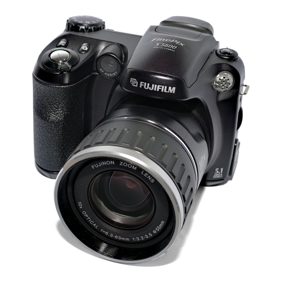
DIGITAL CAMERA
FinePix S5200/
SERVICE MANUAL
" ON THE SCHEMATIC
S5600
Ref.No.:ZM00608-100
Printed in Japan 2005.09
Advertisement
Table of Contents

Summarization of Contents
General Camera Information
Product Specifications Overview
Detailed technical specifications for the FinePix S5200/S5600 digital camera.
Explanation of Technical Terms
Definitions of common photography and camera-related terms used in the manual.
External Component Identification
Labels and locations of all external buttons, ports, and features on the camera.
Camera Disassembly Procedures
Internal Component Identification
Diagram showing the names and locations of key internal parts and assemblies.
Removing Rear Casing
Step-by-step guide for safely removing the rear cover assembly.
Removing Main and Sub PCBs
Instructions for disconnecting and removing the main and sub Printed Circuit Boards.
Schematics and Diagrams
Schematic Cautions
Important safety precautions and notes related to schematic diagrams and component replacement.
Main Block Function Descriptions
Detailed explanations of the operational principles of major functional blocks.
Camera Block Schematic
Schematic for the main imaging and signal processing circuitry.
Process Block Schematic
Schematic for the central processing unit and data handling.
Mounted Parts Diagrams
Component layout diagrams for various Printed Circuit Boards (PCBs).
Camera Adjustment Procedures
Key Adjustments After Part Replacement
Critical adjustments required after replacing major camera components like lens or PWB.
Pattern Box Calibration
Procedure for calibrating the pattern box used in various camera adjustments.
Adjustment Software Setup
Steps for downloading, installing, and preparing the camera adjustment software.
Starting the Adjustment Software
Instructions for launching and navigating the camera adjustment software interface.
Flash Memory Reset Procedure
Procedure for resetting the camera's flash memory, essential after PWB replacement.
CAMERA Adjustment Steps
Detailed steps for adjusting camera settings like shutter, ISO, white balance, and AE.
AF Adjustment Procedure
Procedure for calibrating the autofocus system using specific charts and equipment.
End Setting Configuration
Final configuration steps including destination, USB ID, and product mode settings.
Inspection and Factory Settings
Required Measuring Equipment
List of necessary measuring instruments and jigs for inspection procedures.
Inspection and Factory Settings Checklist
Detailed steps and expected results for performing factory inspections.
Camera Parts List
Packing and Accessories List
Lists all items included in the camera's packaging and optional accessories.
Front Block Parts Identification
Exploded view and part numbers for the front section of the camera assembly.
Rear Block Parts Identification
Exploded view and part numbers for the rear section of the camera assembly.
Electrical Parts Listing
Detailed listing of electrical components, switches, connectors, and fuses by PWB.


Need help?
Do you have a question about the FinePix S5600-CA and is the answer not in the manual?
Questions and answers