Table of Contents
Advertisement
Quick Links
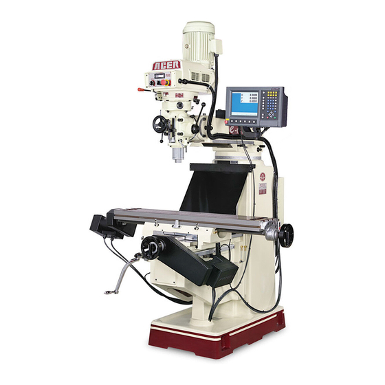
OPERATION MANUAL
Vertical Turret Milling Machine
Model: e-mill 3VS & 3VSII, e-mill 3VK
e-mill 3VKH, e-mill 5VK, e-mill 6VK
Taiwan: Ya-Gin Machine Tool Manufacturing Inc.
No. 101, 506 Lane, Seng-Tso Road,
Seng Karng District, Taichung City, Taiwan
Tel: 886-4-2520-4120
CA: Springwood Industrial, Inc.
2320 E. Valencia Drive
Fullerton, CA 92831
Tel: 714-871-5558
NJ: Klim Industrial, Inc.
244 N. Randolphville Rd.
Piscataway, NJ 08854
Tel: 732-752-9100
Revised: 4/18/19
ACER
w/ Toshiba & Fuji Inverter
Fax: 886-4-2520-4123
Fax: 714-871-5554
Fax: 732-752-9101
- 0 -
Advertisement
Table of Contents

Related Manuals for Acer e-mill 3VK


Summarization of Contents
SAFETY INSTRUCTIONS
General Safety Instructions
General safety guidelines for machine operation and work holding.
Maintenance Safety
Safety precautions for machine servicing, including electrical hazards.
Installation Precautions
Guidelines for safe machine installation, including grounding and environmental conditions.
Operational Safety Precautions
Detailed safety measures for machine operation, warm-up, and handling procedures.
Warning Signs On The Machine
Identification and explanation of warning signs displayed on the machine.
SPECIFICATION
Machine Specification
Detailed specifications and principal dimensions for various e-mill models.
Milling Head Specification
Technical specifications for the milling head, including power and RPM.
Features & Description of Machines
Identification and description of machine parts via numbered diagrams.
INSTALLATION
Lifting Machine
Proper methods and safety precautions for lifting and moving the machine.
Solid Foundation
Requirements for a stable and secure foundation for machine installation.
Leveling Machine
Instructions for precisely leveling the machine using precision levels.
Handles
Note on correct orientation of crank handles for operation.
Connecting Power Supply
Guidelines for safely connecting the machine to the electrical power source.
Wiring Diagram
Electrical diagrams illustrating machine wiring configurations.
LUBRICATION
Lubrication System for 3VS & 3VSII
Diagram and parts list for the lubrication system of 3VS and 3VSII models.
Lubrication System for 3VK
Diagram and parts list for the lubrication system of the 3VK model.
Lubrication System for 3VKH & 5VK
Diagram and parts list for the lubrication system of 3VKH and 5VK models.
Lubrication System for 6VK
Diagram and parts list for the lubrication system of the 6VK model.
Lubrication Schedule
Recommended schedule for lubricating machine areas with specific lubricants.
MSDS for Lubricant
Material Safety Data Sheet for lubricants used in the pump.
OPERATION
Nomenclature
Identification of milling machine parts with diagrams.
Key Operational Controls
Usage of critical controls: Draw Bar, Spindle Brake, F/R Switch, Hi-Lo Lever.
Feed and Movement Controls
Operation of feed mechanisms: power feed, quill feed, and manual handwheels.
Machine Adjustments and Clamping
Procedures for adjusting ram position and clamping table, saddle, and knee.
Operation Recommendations & Safety Accessories
Best practices for milling operations and safety accessories.
MAINTENANCE
Gib Adjustments
Procedures for adjusting table, saddle, and knee gibs for proper fit.
Component Removal and Replacement
Steps for removing motor, changing belts, and replacing springs.
Spare Parts and Maintenance Schedule
Lists of recommended spare parts and a routine maintenance schedule.
Material Cutting Information
Tables of general speed recommendations for cutting various materials.
MECHANICAL DRAWINGS & PARTS LISTS
3HP Milling Head Assemblies
Exploded views and parts lists for 3HP milling head, top housing, and back gear.
5HP Milling Head Assemblies
Exploded views and parts lists for 5HP milling head, hand feed, spindle, auto feed, top housing, back gear.
Basic Machine Assemblies (3VS/3VSII, 3VK, 3VKH, 5VK, 6VK)
Exploded views and parts lists for basic machine chassis and related assemblies.
Leadscrew Assemblies
Exploded views and parts lists for leadscrew assemblies.
Electric Cabinet and Safety Accessories
Exploded views and parts lists for electric cabinet and safety accessories.
Need help?
Do you have a question about the e-mill 3VK and is the answer not in the manual?
Questions and answers