Table of Contents
Advertisement
Quick Links
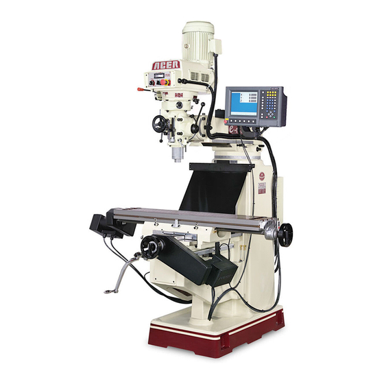
OPERATION MANUAL
Vertical Turret Milling Machine
Model: e-mill 3VS & 3VSII, e-mill 3VK
e-mill 3VKH, e-mill 5VK, e-mill 6VK
Taiwan: Ya-Gin Machine Tool Manufacturing Inc.
No. 101, 506 Lane, Seng-Tso Road,
Seng Karng District, Taichung City, Taiwan
Tel: 886-4-2520-4120
CA: Springwood Industrial, Inc.
2320 E. Valencia Drive
Fullerton, CA 92831
Tel: 714-871-5558
NJ: Klim Industrial, Inc.
244 N. Randolphville Rd.
Piscataway, NJ 08854
Tel: 732-752-9100
Revised: 4/18/19
ACER
w/ Toshiba & Fuji Inverter
Fax: 886-4-2520-4123
Fax: 714-871-5554
Fax: 732-752-9101
- 0 -
Advertisement
Table of Contents


Need help?
Do you have a question about the e-mill 3VKH and is the answer not in the manual?
Questions and answers