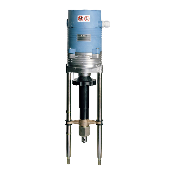
Summarization of Contents
Safety
Proper Use
Defines the intended and unintended uses of the linear actuators.
Information for the Operator
Guidelines for operators on keeping instructions available and observing standards.
Personnel
Specifies requirements for qualified personnel performing tasks on the actuators.
Prior to Starting Work
Instructions on checking type designations before commencing work.
During Operation
Emphasizes safe operation through correct installation, operation, and maintenance.
Working Environment
Refers to technical data for information regarding the working environment.
Product Specification
Components
Lists and illustrates the various components of the linear actuator.
Accessories
Describes optional accessories like printed circuit boards for output signals.
Operating Modes
Explains the two primary operating modes: Manual and Automatic.
Continuous Mode
Details how the actuator position is specified by the system control in Continuous mode.
Three-Point Mode
Explains how movement direction is controlled via voltage on specific terminals.
Functions
Details various functional aspects of the linear actuator.
Binary Signal / Frost Protection Function
Describes the function of terminals B1 and B2 for mode switching and frost protection.
Lock Detection
Explains how the actuator detects and responds to mechanical locking.
Internal Temperature Monitoring
Covers the actuator's internal temperature monitoring and overheating protection.
Open-Circuit Detection
Describes the detection of open circuits in the input signal for specific operating modes.
Set Time
Defines actuating time and how it is set by coding switch S5.
Hysteresis
Explains hysteresis and its purpose in preventing permanent oscillation.
Manual Mode and Feedback Signal
Details manual lift adjustment and feedback signals when in Manual mode.
Autotest
Explains the Autotest function to prevent valve seizing during inactivity.
Autopause
Describes the Autopause function for managing frequent direction changes.
Potential-Free Way-Switch (Optional Extra)
Covers the optional way-switch printed circuit board for setting lift positions.
Technical Data
Presents key technical specifications like voltage, power, weight, and dimensions.
Ratingplate
Explains the information found on the linear actuator's rating plate.
Assembly
Check the Scope of Supply
Steps to verify packaging and completeness of the delivery.
Prepare for Installation
Instructions on preparing the installation site and checking the valve fit.
Mount Linear Actuator on Valve
Detailed steps for mounting the linear actuator onto the valve.
Fit/Remove Cover
Procedures for removing and refitting the actuator's cover.
Connect the Electrics
Instructions and safety precautions for connecting the electrical wiring.
Control-Independent Switching
Explains how to switch the actuator to control-independent using a three-stage switch.
Remove Printed Circuit Board Cover
Steps for removing the printed circuit board cover to access coding switches.
Optional Extras Installation
Information on retrofitting optional extras like way-switch or mA output boards.
Way-Switch Printed Circuit Board Installation
Detailed instructions for installing the way-switch printed circuit board.
Fit the Printed Circuit Board for mA Output Signal
Procedures for fitting the printed circuit board for mA output signals.
Commissioning
Operating Parameters and Coding Switch Positions
How to set operating parameters using coding switches before operation.
Set Input Signal
Instructions for setting the input signal range (voltage or current).
Set Actuating Time
How to set the actuating time using coding switch S5.
Set Hysteresis
Explains how to set hysteresis using trimmer potentiometers P1/P2.
Set Actuating Direction
How to reverse the actuating direction via coding switches S2 and S3.
Set Autotest and Autopause
Describes how to activate and use the Autotest and Autopause functions.
Set Limit Position
How to select the limit position using coding switch S7.
Set Potential-Free Way-Switch
Steps to set the two way-switches using trimmer potentiometers P1/P2.
Initialise the Path-Measuring System
Procedures for initializing the path-measuring system.
Commissioning
A checklist for final steps before the actuator is ready for operation.
Operation
Switching between Manual and Automatic Modes
Instructions for switching between Manual and Automatic operating modes.
Maintenance, Care and Repairs
LED Display
Explains the meaning of the green and red LED indicators for status and faults.
Spare Parts
Guidance on ordering optional extras and spare parts based on rating plate data.
Troubleshooting
Operating Faults Checklist
A detailed checklist of common faults, their causes, and remedies.


Need help?
Do you have a question about the MC503/24 and is the answer not in the manual?
Questions and answers