Sign In
Upload
Download
Table of Contents
Contents
Add to my manuals
Delete from my manuals
Share
URL of this page:
HTML Link:
Bookmark this page
Add
Manual will be automatically added to "My Manuals"
Print this page
×
Bookmark added
×
Added to my manuals
Manuals
Brands
Motorola Manuals
Two-Way Radio
MT553C
Installation manual
Motorola MT553C Installation Manual
Hide thumbs
1
2
3
4
Table Of Contents
5
6
7
8
9
10
11
12
13
14
15
16
17
18
19
20
21
22
23
24
25
26
27
28
29
30
31
32
33
34
35
36
37
38
39
40
41
42
43
44
45
46
47
48
49
50
51
52
53
54
55
56
57
58
59
60
61
62
63
64
65
66
67
68
69
70
71
72
73
74
75
76
77
78
79
80
81
82
83
84
85
86
87
88
89
90
91
92
93
94
95
96
97
98
99
100
101
102
103
104
105
106
107
108
109
110
111
112
113
114
115
116
117
118
119
120
121
122
123
124
125
126
127
128
129
130
131
132
133
134
page
of
134
Go
/
134
Contents
Table of Contents
Bookmarks
Table of Contents
Copyrights
Table of Contents
List of Figures
List of Tables
Icon Conventions
Chapter 1: Scope of this Manual
Safety Information
Mtm5X00 Manuals and User Guides
Chapter 2: Model Information and Accessories
Model Descriptions
Sales Model Nomenclature
Table 1: Radio Model Descriptions
Table 2: Sales Model Nomenclature
Table 3: Sales Models - Description of Symbols
Mobile Terminal Model Information
Table 4: Type and Model Numbers
Model Specifications
Table 5: General Specifications
Table 6: Receiver Specifications
Table 7: Transmitter Specifications
MTM5200/MTM5400 Accessories-To-Model Chart
Table 8: Control Heads
Table 9: Expansion and Remote Head Kits
Table 10: Microphones
Table 11: Loudspeakers
Table 12: Handsets
Table 13: PTT Switches
Table 14: Desktop and Data Box Mount
Table 15: Power Supplies
Table 16: Power Cables
Table 17: Cables
Table 18: Junction Box
Table 19: Power Cables (to Mobile Terminal)
Table 20: Installation
Table 21: Mounting (Transceiver)
Table 22: Mounting (Control Head)
Table 23: Programming/Data
Table 24: Antennas
MTM5500 Accessories-To-Model Chart
Table 25: GPS
Table 26: Motorcycle Enclosures
Table 27: Control Heads
Table 28: Microphones
Table 29: Loudspeakers
Table 30: Handsets
Table 31: PTT Switches
Table 32: Cables
Table 33: Power Cables (to Mobile Terminal)
Table 34: Installation
Table 35: Mounting (Transceiver)
Table 36: Mounting (Control Head)
Table 37: Programming/Data
Table 38: Antennas
Table 39: GPS
Table 40: Label Identification for Telephone Style Control Head
Table 41: Ferrites for Ethernet Control Head
Chapter 3: Vehicle Preparation
General Guidelines for Radio Installation
Uninstalling the Radio
Installing DC Power Cable
Figure 1: Power Cabling Routing to Engine Compartment
Figure 2: Power Cable Assembly
DC Power Cables
Installing Ignition Sense Cable
Table 42: DC Power Cables
Figure 3: Accessory Plug
Ignition Sense Cables
Table 43: Ignition Sense Cables
Chapter 4: Radio Installation
Dashboard Installation
Installing the Radio in an Automotive Dashboard
Mounting the Radio in the Frame
Removing the Radio from the Frame
Figure 4: Radio with Mount Kit
Desktop Installation
Desktop Installation Planning
Figure 5: Radio with Demount Tools
Figure 6: Typical Desktop Mounting
MTM5200/MTM5400 Remote Mount Installation
Figure 7: Remote Mount Installation with Remote Head Enhanced/Data Expansion Head
Table 44: Associated Components
Installing the Remote Mount Enhanced Control Head Onto the Remote Mount Trunnion
Table 45: Associated Components for Remote Mount
Figure 8: Remote Mount Enhanced Control Head Installation with Remote Mount Trunnion
Installing the Remote Mount Enhanced Control Head in a DIN Mount Bracket
Figure 9: Remote Mount Enhanced Control Head Installation with DIN Mount Bracket
Inserting the Remote Mount Enhanced Control Head with the DIN Mount Bracket into the DIN Frame
Adding Extra Accessories to the Remote Head by Expansion Cable
Figure 10: Radio with Mounting Bracket and Mounting Kit
Installing the Accessories Expansion Cable
MTM5500 Remote Mount Installation
Figure 11: Accessories Expansion Cable with the Mobile Microphone Port (MMP)
Figure 12: Remote Mount Installation with Ethernet Control Head (Ech) PMWN4024
Table 46: MTM5500 Configurations - Graphics Description
Figure 13: Remote Mount Installation with Ethernet Telephone Style Control Head (TSCH)
Figure 14: Dual Control Head with Two Ech
Figure 15: Dual Control Head with Two TSCH
Figure 16: Dual Control Head with a Combination of Ech and TSCH
Figure 17: Multi Radio Control Installation with Ech
Figure 18: Multi Radio Control Installation with TSCH
Ethernet Cables
Figure 19: Ethernet Cable
Figure 20: Ethernet Cable (PMKN4135_)
Table 47: Ethernet Cables
Figure 21: Ethernet Cable (PMKN4176_, PMKN4177_, and PMKN4178_)
Installing the Remote Mount Ethernet Control Head (Ech) Onto the Remote Mount Trunnion
Figure 22: Remote Mount Enhanced Control Head Installation with Remote Mount Trunnion
Installing the Remote Mount Ethernet Control Head (Ech) in a DIN Mount Bracket
Figure 23: Remote Mount Enhanced Control Head Installation with DIN Mount Bracket
Inserting the Remote Mount Ethernet Control Head (Ech) with the DIN Mount Bracket into the DIN Frame
Adding Extra Accessories to the Ethernet Control Head (Ech) and Telephone Style Control Head (TSCH)
Figure 24: Mounting the Remote Mount Enhanced Control Head with the DIN Mount Bracket into
Figure 25: Accessories Expansion RECH Y-Cable
Figure 26: Accessories Expansion TSCH Y-Cable
Telephone Style Control Head (TSCH)
Figure 27: Telephone Style Control Head (TSCH) Cradle
Figure 28: TSCH Handset and Cradle
Figure 29: TSCH Unsupported Installation
Figure 30: Slim Bracket
Mounting TSCH Cradle Onto Slim Bracket
Figure 31: Rear View of TSCH Cradle
Figure 32: Rear View of the TSCH Cradle with Slim Bracket
Motorcycle Mount Enhanced Control Head Installation
Figure 33: Rear View of the TSCH Cradle with Attached Slim Bracket
Figure 34: Motorcycle Mount Enhanced Control Head - Front Side
Installing Motorcycle Mount Enhanced Control Head
Figure 35: Motorcycle Installation
Figure 36: Upward Movement
Figure 37: Downward Movement
Figure 38: Motorcycle Mount Enhanced Control Head Mounted in a Trunnion
Installing Motorcycle Mount TELCO Cable (PMKN4030_)
MTM5200/MTM5400 Mechanical Parts
Table 48: Motorcycle Mount Enhanced Control Head - Mechanical Parts List for Installation
Adding Extra Connectivity to the Motorcycle Mount Enhanced Control Head
Data Expansion Head Enhanced Installation
Data Expansion Head Enhanced Radio Without Control Head
Data Box Radio
Figure 39: Data Box Radio Interface Description
Data Expansion Head Enhanced with 3Rd Party Control Head
Figure 40: Configuration with Two Control and Data Terminals
Junction Box Installation
Figure 41: Remote Mount Installation with Junction Box
Installing Junction Box
Connecting Accessories to the Junction Box
Connectors on the Junction Box
Figure 42: Connectors on the Junction Box - Front Panel
Connection Plan for the Junction Box Accessory Terminal
Figure 43: Connectors on the Junction Box - Rear Panel
Figure 44: Connection Plan for the Speaker
Figure 45: Connection Plan for the Alarm Relay
Figure 46: Connection Plan for the Emergency Switch
Installing the Cable
Figure 47: Connection Plan for the Ignition Sense Cable
Figure 48: Connection Plan for External PTT
Connection Plan for Accessory Connector Kit
Table 49: Accessory Connector Kit - Cable Connectivity
Radios with Data Expansion Head Enhanced
Standard Radios Without Data Expansion Head Enhanced
Standard Radios Without Ethernet Data Expansion Head
Installing Trunnion
Figure 49: Terminal into High Profile Trunnion (GLN7317_)
Figure 50: Terminal into Key Locked Mount Trunnion (RLN4779_)
Figure 51: Top of Dash Mount
Figure 52: below Dash Mounting
Chapter 5: Connectors and PIN Assignment
Transceiver Rear Side
Figure 53: Location of Accessory Connector - Rear Side
Table 50: 26-PIN Accessory Connector
Accessory Connection Plan
Figure 54: Accessory Connector
Figure 55: 26-Pin Accessory Connector
Re-Crimp Procedure
Figure 56: Connecting Diagrams
Connectors and Pin Assignment of Data Expansion Head Enhanced and Remote Head Enhanced
Figure 57: Data Expansion Head Enhanced - Front View and Connector Location
10-Pin TELCO Connector
Figure 58: Remote Head Enhanced - Front View and Connector Location
Table 51: 10-Pin TELCO Connector Pins
25-Pin Subd Connector
Table 52: 25-Pin Subd Connector Pins
9-Pin Subd Connector
Table 53: 9-Pin Subd Connector Pins
Connectors and Pin Assignment of Ethernet Expansion Head
Ethernet Control Head Interfaces
Figure 59: Ethernet Expansion Head Enhanced - Front View and Connector Location
Table 54: Pin Assignment of the 10-Pin RJ50 Port 1 and Port 2 Connector - Ethernet Expansion
9-Pin Subd Connector
Connector and Pin Assignment of the Enhanced Control Head
Figure 60: Enhanced Control Head's Mobile Microphone Port Connector
Table 55: 9-Pin Subd Connector Pins
Figure 61: Enhanced Motorcycle Control Head -Rear View
Table 56: Enhanced Control Head`s Mobile Microphone Port Connector
Figure 62: Remote Enhanced Control Head - Rear View
Figure 63: Enhanced Motorcycle Control Head - Rear Connectors
Table 57: 10-Pin Telco Connector
Table 58: 25-Pin Back Connector
Connector and Pin Assignment of Ethernet Control Head (Ech)
Figure 64: View of the Ethernet Control Head (Ech) with Mobile Microphone Port Connector
Figure 65: Ethernet Control Head - Rear Connectors
Table 59: Mobile Microphone Port Connector
Table 60: 10-Pin Ethernet Connector
Table 61: 25-Pin Back Connector
Connecting Cables
Motorcycle Mount TELCO Cable
Figure 66: Motorcycle Mount TELCO Cable
Remote Mount Cables
Accessories Expansion Cable
Figure 67: Remote Mount Cable
Figure 68: Accessories Expansion Cable
Table 62: Accessories Expansion Cable - Connections
Connector and Pin Assignment for Cradle (Telephone Style Control Head)
Table 63: Pin Assignment of the 10-Pin Audio Connector - Telephone Style Control Head
Table 64: Pin Assignment of the 10-Pin RJ50 Connector - Telephone Style Control Head
Ethernet Cables
Remote Ethernet Control Head Y-Cable (Accessories Expansion Cable)
Figure 69: Mobile to Control Head Ethernet Cable Pin Diagram
Figure 70: Mobile to Mobile Ethernet Cable Pin Diagram
Telephone Style Control Head Y-Cable (Accessories Expansion Cable)
Radio-To-Junction Box
Figure 71: RECH Y-Cable Pin Diagram
Figure 72: TSCH Y-Cable Pin Diagram
Figure 73: Connecting Cable - Radio-To-Junction Box
Data Expansion Head Enhanced Radio-To-Data Device
Data Expansion Head Enhanced Radio-To-Fist Microphone
Figure 74: Standardized RS232 Cable
Removing the Existing Coiled Cord Cable
Figure 75: Pin Assignment of Cable from Accessory Connector to Microphone Housing
Table 65: Pin Assignment of Cable from Accessory Connector to Microphone Housing
Cables to Provision AIE/E2E Keys
Figure 76: Active Data Cable PMKN4104
Table 66: Pin Assignment - Active Data Cable PMKN4104
Chapter 6: External Equipment Installation
Vehicle Antenna Installation
Mobile Radio Operation and EME Exposure
Selecting an Antenna Site
Installing Antenna
Figure 77: Connections to the Rear Side of the Radio
Completing Radio Installation
Installing External Speaker
Figure 78: External Speaker Trunnion Bracket
Appendix A: Service Information - EIA
Table 67: Service Information - Telephone Numbers to EIA Integrated Call Center
Appendix B: Service Information - AME
Table 68: Service Information - Telephone Numbers and Addresses of the Asia and Pacific Motorola Centers
Piece Parts
Appendix C: Service Information - Americas
Table 69: Service Information - Telephone Numbers and Addresses of Latin America Radio Support Centers
Table 70: Service Information - Telephone Numbers and Addresses of Latin America Motorola Centers
Appendix D: Warranty and Service Support
Appendix E: Product Specific Information for Digital Terminals Type MT953C/MT853C/MT753C/MT553C
Table 71: Equipment Electrical Ratings
Table 72: Normal Load Conditions
Advertisement
Quick Links
Download this manual
MTM5x00 Installation
Manual
JANUARY 2016
*68015000181*
68015000181-LB
© 2016 Motorola Solutions, Inc. All rights reserved
Työpajatie 13a | 06150 Porvoo | +358 19 574 5700 | www.malux.fi
Table of
Contents
Previous
Page
Next
Page
1
2
3
4
5
Advertisement
Table of Contents
Need help?
Do you have a question about the MT553C and is the answer not in the manual?
Ask a question
Questions and answers
Related Manuals for Motorola MT553C
Two-Way Radio Motorola MT500 H23BBB User Manual
Fm two-way portable radio (79 pages)
Two-Way Radio Motorola MT500 Series Operating Instructions Manual
Fm two-way portable radio (16 pages)
Two-Way Radio Motorola MTP850 Ex Product Information Manual
Tetra handportable terminal (294 pages)
Two-Way Radio Motorola TETRA MTH800 Basic Service Manual
Handportable terminal 380-430 mhz/440-470 mhz (102 pages)
Two-Way Radio Motorola MTP850 Basic User's Manual
Tetra portable terminal (334 pages)
Two-Way Radio Motorola MTP850 S Feature User Manual
(128 pages)
Two-Way Radio Motorola MTP850 Feature User Manual
(128 pages)
Two-Way Radio Motorola MTP850 S Product Information Manual
(112 pages)
Two-Way Radio Motorola HT Series Service Manual
Professional series two-way portable radio (122 pages)
Two-Way Radio Motorola HT Series Detailed Service Manual
Professional series two-way portable radios (96 pages)
Two-Way Radio Motorola MTP8500Ex User Manual
Tetra atex series (352 pages)
Two-Way Radio Motorola XTS 2500 Service Manual
(914 pages)
Two-Way Radio Motorola MTP830 User Manual
(108 pages)
Two-Way Radio Motorola MT953C Installation Manual
(134 pages)
Two-Way Radio Motorola MTP8550Ex Feature User Manual
(176 pages)
Two-Way Radio Motorola MTM800 E Feature User Manual
(216 pages)
Summarization of Contents
Scope of This Manual
Safety Information and User Guides
Covers RF energy exposure, installation safety requirements, and related manuals.
Model Information and Accessories
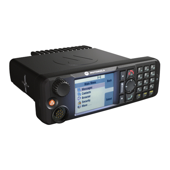
Model Descriptions and Specifications
Details radio models, nomenclature, specifications, and accessories.
MTM5x00 Accessories
Lists accessories compatible with MTM5200/MTM5400 and MTM5500 models.
Vehicle Preparation
General Installation Guidelines
General instructions for radio installation in vehicles.
Radio Removal and Cable Installation
Procedures for uninstalling the radio and installing power/ignition cables.
Radio Installation
Dashboard and Desktop Installation
Steps for installing the radio in a dashboard or as a desktop unit.
MTM5200/MTM5400 Remote Mount Installation
Procedures for remote mount setups of MTM5200/MTM5400.
MTM5500 Remote Mount Installation
Procedures for MTM5500 remote mount and related head installations.
Motorcycle Mount Installation
Instructions for installing the radio on a motorcycle.
Data Expansion Head and Junction Box Installation
Covers Data Expansion Head and Junction Box setup.
Connectors and PIN Assignment
Transceiver Rear Side Connectors
Details the 26-pin accessory connector on the transceiver rear.
Accessory Connection Plan and Diagrams
Shows connection plans for accessories and wiring diagrams.
Data/Remote Head Connector Pin Assignments
Pin assignments for Data Expansion and Remote Heads.
Ethernet Expansion Head Connector Pin Assignments
Pin assignments for Ethernet Expansion Head interfaces.
Enhanced/Ethernet Control Head Connector Pin Assignments
Pin assignments for Enhanced and Ethernet Control Heads.
Connecting Cables and Pin Diagrams
Details various cables and their pin assignments.
External Equipment Installation
Vehicle Antenna Installation
Guidelines for installing vehicle antennas and selecting sites.
External Speaker Installation
Procedures for mounting and connecting an external speaker.
Service Information – EIA
European Support Centers and Contact Information
Contact details for ERSC and ESCC in Europe.
Service Information – AME
Asia/Pacific Support Centers and Contact Info
Contact details for service centers in Asia and Pacific regions.
Service Information – Americas
Latin America and Caribbean Support Centers
Contact details for service centers in Latin America and Caribbean.
Warranty and Service Support
How to Obtain Warranty Service
Steps and information for getting warranty service.
Product Specific Information for Digital Terminals
Electrical Ratings and Fuse Information
Details electrical ratings and fuse specifications for terminals.
Table of Contents
Save PDF
Print
Rename the bookmark
Delete bookmark?
Delete from my manuals?
Login
Sign In
OR
Sign in with Facebook
Sign in with Google
Upload manual
Upload from disk
Upload from URL
Need help?
Do you have a question about the MT553C and is the answer not in the manual?
Questions and answers