Sign In
Upload
Download
Table of Contents
Contents
Add to my manuals
Delete from my manuals
Share
URL of this page:
HTML Link:
Bookmark this page
Add
Manual will be automatically added to "My Manuals"
Print this page
×
Bookmark added
×
Added to my manuals
Manuals
Brands
Hioki Manuals
Medical Equipment
IM7587
Instruction manual
Hioki IM7587 Instruction Manual
Impedance analyzer
Hide thumbs
1
2
Table Of Contents
3
4
5
6
7
8
9
10
11
12
13
14
15
16
17
18
19
20
21
22
23
24
25
26
27
28
29
30
31
32
33
34
35
36
37
38
39
40
41
42
43
44
45
46
47
48
49
50
51
52
53
54
55
56
57
58
59
60
61
62
63
64
65
66
67
68
69
70
71
72
73
74
75
76
77
78
79
80
81
82
83
84
85
86
87
88
89
90
91
92
93
94
95
96
97
98
99
100
101
102
103
104
105
106
107
108
109
110
111
112
113
114
115
116
117
118
119
120
121
122
123
124
125
126
127
128
129
130
131
132
133
134
135
136
137
138
139
140
141
142
143
144
145
146
147
148
149
150
151
152
153
154
155
156
157
158
159
160
161
162
163
164
165
166
167
168
169
170
171
172
173
174
175
176
177
178
179
180
181
182
183
184
185
186
187
188
189
190
191
192
193
194
195
196
197
198
199
200
201
202
203
204
205
206
207
208
209
210
211
212
213
214
215
216
217
218
219
220
221
222
223
224
225
226
227
228
229
230
231
232
233
234
235
236
237
238
239
240
241
242
243
244
245
246
247
248
249
250
251
252
253
254
255
256
257
258
259
260
261
262
263
264
265
266
267
268
269
270
271
272
273
274
275
276
277
278
279
280
281
282
283
284
285
286
287
288
289
290
291
292
293
294
295
296
297
298
299
300
301
302
303
304
305
306
307
308
309
310
311
312
313
314
315
316
317
318
319
320
321
322
323
324
325
326
327
328
329
330
331
332
333
334
335
336
337
338
339
340
341
342
343
344
page
of
344
Go
/
344
Contents
Table of Contents
Troubleshooting
Bookmarks
Table of Contents
Table of Contents
Im7580A
Options (Sold Separately)
Safety Information
Operating Precautions
Overview
Overview and Features
Names and Functions of Parts
Screen Operations
Measurement Preparations
Connecting the Test Head
Pre-Operation Inspection
Connecting the Power Cord
Connecting a Measurement Cable/Fixture
Connecting an Interface
Turning the Power on and off
Select the Measurement Mode
LCR Function
Flowchart
Screen Map
Measurement Screen
Status and Error Display of this Instrument
Setting Basic Settings of Measurement Conditions
Setting Display Parameters
Starting Measurement at any Arbitrary Timing (Trigger)
Setting the Delay Time from Trigger to Measurement Start (Trigger Delay)
Applying the Signal to the Sample During Measurement Only (Trigger Synchronous Output)
Setting the Measurement Frequency
Setting the Measurement Signal Level
Setting the Measurement Speed
Display with Average Values (Average)
Judging Measurement Results
Setting the Judgment Mode
Judging with Upper and Lower Limit Values (Comparator Judgment Mode)
Classifying Measurement Results (bin Judgment)
Analyzer Function
Flowchart
Screen Map
Measurement Screen
Types of Graph
Status and Error Display of this Instrument
Setting Basic Settings of Measurement
Setting the Measurement Parameters
Starting Measurement at any Arbitrary Timing (Trigger)
Setting the Delay Time from Trigger to Measurement Start (Trigger Delay)
Applying the Signal to the Sample During Measurement Only (Trigger Synchronous Output)
Setting the Sweep Parameter
Sweep Measurement
Setting the Sweep Method
Setting the Sweep Range
Normal Sweep
Segment Sweep and Segment Interval Sweep
Set Measurement Conditions for Sweep Points
Setting the Measurement Signal Frequency
Setting the Measurement Signal Level
Setting the Measurement Speed
Displaying Average Values (Average)
Setting the Delay Time for each Sweep Point (Point Delay)
Setting the Graph Display Method
Setting the Horizontal Axis
Setting the Vertical Axis
Configuring the X-Y Display Vertical Axis Reversal Setting
Setting The X-Y Display Scale Width
Setting Grid Display
Setting Overlay
Setting the Cursor
Selecting the Cursor to Display in the Screen
Setting Cursor Move
Performing Measurement Value Search
Setting the Search Target Parameter
Setting the Search Type
Using the Automatic Search Function
Executing Search
Judging Measurement Results (Comparator Function)
Setting the Judgment Mode
Setting the Parameter to be Judged (Spot Judgment Excluded)
Setting the Judgment Area to Display in the Measurement Screen (Spot Judgment Excluded)
Area Judgment
Peak Judgment
Spot Judgment
Equivalent Circuit Analysis Function
Configuring Basic Settings For Analysis
Performing Equivalent Circuit Analysis
Simulating Frequency Characteristics
Settings to Judge Analysis Results
Calibration and Compensation
Calibration and Compensation Function Overview
Calibration
Setting Calibration Conditions and Executing Calibration [CAL]
Error Compensation
Setting the Electric Length Compensation [LENGTH]
Setting Compensation Conditions and Executing Compensation [COMPEN]
Calculating Values (Scaling)
Troubleshooting of Compensation
Continuous Measurement Function
Continuous Measurement
Operation Flow
Measurement Screen
Configuring Continuous Measurement Basic Settings
Executing and Stopping Continuous Measurement
Checking Continuous Measurement Results
Cancels the Measurement if an Error Is Detected
Application Function
Checking Contact Defects and the Contact State (Contact Check Function)
Setting the DC Measurement
Setting the Judgment
Detecting OPEN During 2-Terminal Measurement (Hi Z Reject Function)
Monitoring the Detection Level (Detection Level Monitoring Function)
Other Functions
Set the Number of Display Digits
Setting Absolute Value Display (LCR Only)
Setting the Communication Measurement Data Type
Common Functions (LCR Mode, ANALYZER Mode)
Saving Measurement Results (Memory Function)
Setting the Screen Display
Setting the Beep Sound
Display The Warm-Up Message
Disabling Key Operation (Key-Lock Function)
Setting the Communication Measurement Data Type
Initializing the Instrument (System Reset)
External Control
External Input/Output Connector and Signals
Timing Chart
LCR Mode
Analyzer Mode
CONTINUOUS Measurement Mode
Internal Circuit
External Control Q&A
Measurement Using a Computer
External Control I/O Settings
Enabling Trigger Input During Measurement (Trigger Enabled)
Setting Valid Edge of Trigger Input (Trigger Edge)
Setting Reset of Judgment Results (Judgment Result Signal Reset)
Setting the EOM Output Method (EOM Mode)
Setting Delay Time from Judgment Results Output until Output of EOM (LOW) (JUDGE-EOM)
S Et a Delay for INDEX Signal Output (INDEX Delay)
Saving and Loading Panel Information
Saving Measurement Conditions (Panel Save Function)
Loading Measurement Conditions (Panel Load Function)
Changing a Panel Name
Deleting a Panel
Setting the SYSTEM
Setting the Interface
Checking the Instrument Version
Self Checks (Self Diagnosis)
Panel Test
Panel Compensation
Screen Display Test
ROM/RAM Test
I/O Test
Setting the Date and Time
Using USB Flash Drive
Overview
Inserting and Removing USB Flash Drive
Screen Display When Using USB
Saving Data to USB Flash Drive
Saving Measurement Result as Text
Saving Measurement Screen (Screen Copy)
Setting Save Folder
Saving Memory Data
Saving Instrument Settings to USB Flash Drive
Saving Instrument Settings
Saving All Settings of Instrument (ALL SAVE Function)
Loading Binary Data from USB Flash Drive
Loading Measurement Data (ANALYZER Function)
Loading Instrument Settings
Loading All Settings (ALL LOAD Function)
Editing Data Saved in USB Flash Drive
Formatting a USB Flash Drive
Creating a Folder in USB Flash Drive
Changing Folder Name or File Name in USB Flash Drive
Deleting a File or Folder in USB Flash Drive
Checking The Contents Of Files
Specifications
General Specifications
Measurement Specifications
Functional Specification
Interface Specifications
Measurement Accuracy
Example: Calculation of Accuracy
Measurable Range
Maintenance and Service
Inspection, Repair and Cleaning
Disposal
Troubleshooting
Error Display
Appendix A1
Appx. 1 Measurement Parameters
Appx. 2 Countermeasures to
Noise from the Power Supply Line
X84; Countermeasures to Prevent Entry Noise from the Measurement Cables
Appx. 3 Series Equivalent Circuit
Equivalent Circuit Mode
Appx. 4 Selecting the Equivalent
Circuit Model
Appx. 5 Maintenance of Coaxial Connector
Appx. 6 Rack Mounting
X84; Installation Procedure
Appx. 7 Dimensional Diagram
Introduction
Verifying Package Contents
Advertisement
Quick Links
1
Im7580A
2
Options (Sold Separately)
3
Measurement Preparations
4
Calibration and Compensation
Download this manual
IM7580A
IM7581
IM7583
IM7585
IM7587
IMPEDANCE ANALYZER
Sept. 2018 Revised edition 4
IM7585A981-04 18-09H
IM7580A-1
IM7580A-2
IM7581-01
IM7581-02
IM7583-01
IM7583-02
IM7585-01
IM7585-02
IM7587-01
IM7587-02
Instruction Manual
EN
Table of
Contents
Previous
Page
Next
Page
1
2
3
4
5
Advertisement
Table of Contents
Troubleshooting
Troubleshooting of Compensation
170
Troubleshooting
313
Need help?
Do you have a question about the IM7587 and is the answer not in the manual?
Ask a question
Questions and answers
Related Manuals for Hioki IM7587
Medical Equipment Hioki IM7580A Instruction Manual
Impedance analyzer (344 pages)
Medical Equipment Hioki 3155 User Manual
(51 pages)
Summarization of Contents
1 Overview
1.1 Overview and Features
Provides a general introduction to the instrument and its key features.
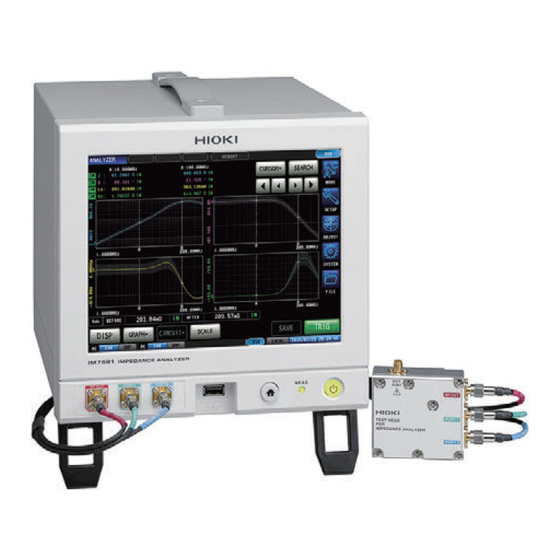
1.2 Names and Functions of Parts
Identifies and describes the front, rear, and side panels of the instrument.
1.3 Screen Operations
Explains how to navigate and interact with the instrument's touch panel display.
2 Measurement Preparations
2.1 Connecting the Test Head
Details the procedure for connecting the test head to the instrument.
2.2 Pre-Operation Inspection
Outlines the necessary checks before operating the instrument.
2.3 Connecting the Power Cord
Provides instructions for connecting the power cord to the instrument.
2.4 Connecting a Measurement Cable/Fixture
Explains how to connect measurement cables or test fixtures.
2.5 Connecting an Interface
Describes how to install and connect optional interface modules.
2.6 Turning the Power ON and OFF
Details the procedure for powering the instrument on and off.
2.7 Select the Measurement Mode
Explains how to choose between LCR, ANALYZER, and CONTINUOUS modes.
3 LCR Function
3.1 LCR Function
Covers measuring impedance, phase angle, and other parameters in single condition.
3.2 Setting Basic Settings of Measurement Conditions
Guides on setting fundamental measurement parameters like frequency, level, and speed.
3.3 Judging Measurement Results
Explains how to use comparator and BIN functions for pass/fail judgments.
4 Analyzer Function
4.1 Analyzer Function
Describes performing measurements while sweeping frequency and signal level.
4.2 Setting Basic Settings of Measurement
Covers setting parameters for sweep measurements, triggers, and delays.
4.3 Sweep measurement
Details setting sweep range, sweep points, and sweep methods.
4.5 Setting the Graph Display Method
Explains how to configure graph axes, scaling, grid, and overlay settings.
4.6 Setting the Cursor
Guides on displaying and moving cursors on the measurement screen.
4.7 Performing Measurement Value Search
Covers using search functions to find specific measurement values.
4.8 Judging Measurement Results (Comparator Function)
Explains area, peak, and spot judgment methods for analysis results.
4.9 Equivalent Circuit Analysis Function
Details estimating circuit constants using models and simulating characteristics.
5 Calibration and Compensation
5.1 Calibration and Compensation Function Overview
Explains the necessity and timing of calibration and compensation procedures.
5.2 Calibration
Guides on setting calibration conditions and executing open/short/load calibration.
5.3 Error Compensation
Covers setting electric length and compensation conditions.
5.4 Calculating Values (Scaling)
Explains how to use the scaling function to compensate measurement values.
5.5 Troubleshooting of Compensation
Provides solutions for common errors during calibration and compensation.
6 Continuous Measurement Function
6.1 Continuous Measurement Function
Describes performing sequential measurements using saved panel settings.
6.2 Configuring Continuous Measurement Basic Settings
Guides on selecting and configuring panels for continuous measurement.
6.3 Executing and Stopping Continuous Measurement
Explains how to start and stop continuous measurement sequences.
6.5 Cancels the Measurement if an Error is Detected
Details how to automatically cancel measurement upon detecting errors.
7 Application function
7.1 Checking Contact Defects and the Contact State (Contact Check Function)
Covers detecting contact issues and setting check timings.
7.2 Other Functions
Includes settings for display digits, absolute value display, and communication data.
7.3 Common Functions (LCR Mode, ANALYZER Mode)
Covers common settings like saving results, screen display, and beep sound.
8 External Control
8.1 External Input/Output Connector and Signals
Details the EXT I/O connector, pinouts, and signal functions.
8.2 Timing Chart
Provides timing examples for LCR, ANALYZER, and CONTINUOUS modes.
8.3 Internal Circuit
Shows the internal circuit diagrams for input and output signals.
8.4 External Control Q&A
Answers common questions regarding external control connections and issues.
8.6 External Control I/O Settings
Covers enabling trigger input, setting trigger edge, and reset functions.
9 Saving and Loading Panel Information
9.1 Saving Measurement Conditions (Panel Save Function)
Guides on saving measurement conditions and compensation values to memory.
9.2 Loading Measurement Conditions (Panel Load Function)
Explains how to load previously saved measurement conditions.
9.3 Changing a Panel Name
Details the procedure for renaming saved panel data.
9.4 Deleting a Panel
Provides instructions on how to delete saved panel data.
10 Setting the SYSTEM
10.1 Setting the Interface
Covers configuring USB, LAN, GP-IB, and RS-232C interface settings.
10.2 Checking the Instrument Version
Explains how to display and check the instrument's software version.
10.3 Self Checks (Self Diagnosis)
Guides on performing panel tests, compensation, and ROM/RAM checks.
10.4 Setting the Date and Time
Details how to set the instrument's internal date and time.
11 Using USB Flash Drive
11.1 Overview
Introduces saving and loading measurement data via USB flash drive.
11.2 Inserting and Removing USB Flash Drive
Provides instructions on handling USB flash drives with the instrument.
11.4 Saving Data to USB Flash Drive
Covers saving measurement results, screen copies, and memory data.
11.5 Saving Instrument Settings to USB Flash Drive
Guides on saving instrument settings and all settings to USB.
11.6 Loading Binary Data from USB Flash Drive
Explains how to load analyzer data and instrument settings from USB.
11.7 Editing Data Saved in USB Flash Drive
Covers formatting, creating folders, renaming, and deleting files.
12 Specifications
12.1 General Specifications
Provides general specifications like operating environment and power supply.
12.2 Measurement Specifications
Details measurement items, display ranges, frequencies, and accuracy.
12.3 Functional specification
Outlines functional specifications for LCR, Analyzer, and Continuous modes.
12.4 Interface Specifications
Lists specifications for display, handler, communication, and USB interfaces.
12.5 Measurement Accuracy
Provides examples and formulas for calculating measurement accuracy.
13 Maintenance and Service
13.1 Inspection, Repair and Cleaning
Covers instrument inspection, handling of warnings, and cleaning procedures.
13.2 Disposal
Provides instructions for the safe disposal of the instrument and battery.
13.3 Troubleshooting
Lists common instrument malfunctions and their solutions.
13.4 Error Display
Explains various error messages and their corresponding solutions.
Appx. 1 Measurement Parameters and Calculation Formula
Appx. 2 Countermeasures to Prevent Entry of External Noise
Appx. 3 Series Equivalent Circuit Mode and Parallel Equivalent Circuit Mode
Appx. 4 Selecting the Equivalent Circuit Model
Appx. 5 Maintenance of Coaxial Connector
Appx. 6 Rack Mounting
Installation procedure
Provides steps for installing the instrument using rack mounting brackets.
Appx. 7 Dimensional Diagram
Table of Contents
Print
Rename the bookmark
Delete bookmark?
Delete from my manuals?
Login
Sign In
OR
Sign in with Facebook
Sign in with Google
Upload manual
Upload from disk
Upload from URL
Need help?
Do you have a question about the IM7587 and is the answer not in the manual?
Questions and answers