Sign In
Upload
Manuals
Brands
Hioki Manuals
Medical Equipment
IM7587
Hioki IM7587 Manuals
Manuals and User Guides for Hioki IM7587. We have
1
Hioki IM7587 manual available for free PDF download: Instruction Manual
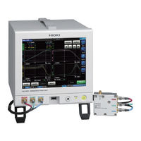
Hioki IM7587 Instruction Manual (344 pages)
Impedance analyzer
Brand:
Hioki
| Category:
Medical Equipment
| Size: 20.71 MB
Table of Contents
Table of Contents
3
Im7580A
9
Options (Sold Separately)
10
Safety Information
10
Operating Precautions
13
Overview
17
Overview and Features
17
Names and Functions of Parts
19
Screen Operations
22
Measurement Preparations
25
Connecting the Test Head
25
Pre-Operation Inspection
27
Connecting the Power Cord
28
Connecting a Measurement Cable/Fixture
29
Connecting an Interface
30
Turning the Power on and off
32
Select the Measurement Mode
33
LCR Function
35
Flowchart
35
Screen Map
36
Measurement Screen
38
Status and Error Display of this Instrument
39
Setting Basic Settings of Measurement Conditions
40
Setting Display Parameters
40
Starting Measurement at any Arbitrary Timing (Trigger)
41
Setting the Delay Time from Trigger to Measurement Start (Trigger Delay)
42
Applying the Signal to the Sample During Measurement Only (Trigger Synchronous Output)
43
Setting the Measurement Frequency
45
Setting the Measurement Signal Level
46
Setting the Measurement Speed
48
Display with Average Values (Average)
49
Judging Measurement Results
51
Setting the Judgment Mode
52
Judging with Upper and Lower Limit Values (Comparator Judgment Mode)
54
Classifying Measurement Results (bin Judgment)
61
Analyzer Function
67
Flowchart
68
Screen Map
70
Measurement Screen
72
Types of Graph
73
Status and Error Display of this Instrument
74
Setting Basic Settings of Measurement
75
Setting the Measurement Parameters
75
Starting Measurement at any Arbitrary Timing (Trigger)
76
Setting the Delay Time from Trigger to Measurement Start (Trigger Delay)
77
Applying the Signal to the Sample During Measurement Only (Trigger Synchronous Output)
78
Setting the Sweep Parameter
80
Sweep Measurement
81
Setting the Sweep Method
82
Setting the Sweep Range
84
Normal Sweep
89
Segment Sweep and Segment Interval Sweep
92
Set Measurement Conditions for Sweep Points
95
Setting the Measurement Signal Frequency
95
Setting the Measurement Signal Level
96
Setting the Measurement Speed
98
Displaying Average Values (Average)
98
Setting the Delay Time for each Sweep Point (Point Delay)
99
Setting the Graph Display Method
100
Setting the Horizontal Axis
100
Setting the Vertical Axis
103
Configuring the X-Y Display Vertical Axis Reversal Setting
106
Setting The X-Y Display Scale Width
107
Setting Grid Display
108
Setting Overlay
109
Setting the Cursor
110
Selecting the Cursor to Display in the Screen
110
Setting Cursor Move
111
Performing Measurement Value Search
112
Setting the Search Target Parameter
112
Setting the Search Type
113
Using the Automatic Search Function
114
Executing Search
115
Judging Measurement Results (Comparator Function)
116
Setting the Judgment Mode
116
Setting the Parameter to be Judged (Spot Judgment Excluded)
118
Setting the Judgment Area to Display in the Measurement Screen (Spot Judgment Excluded)
119
Area Judgment
120
Peak Judgment
124
Spot Judgment
128
Equivalent Circuit Analysis Function
133
Configuring Basic Settings For Analysis
134
Performing Equivalent Circuit Analysis
141
Simulating Frequency Characteristics
144
Settings to Judge Analysis Results
146
Calibration and Compensation
149
Calibration and Compensation Function Overview
149
Calibration
153
Setting Calibration Conditions and Executing Calibration [CAL]
153
Error Compensation
162
Setting the Electric Length Compensation [LENGTH]
162
Setting Compensation Conditions and Executing Compensation [COMPEN]
163
Calculating Values (Scaling)
168
Troubleshooting of Compensation
170
Continuous Measurement Function
171
Continuous Measurement
171
Operation Flow
172
Measurement Screen
173
Configuring Continuous Measurement Basic Settings
174
Executing and Stopping Continuous Measurement
175
Checking Continuous Measurement Results
176
Cancels the Measurement if an Error Is Detected
177
Application Function
179
Checking Contact Defects and the Contact State (Contact Check Function)
179
Setting the DC Measurement
179
Setting the Judgment
182
Detecting OPEN During 2-Terminal Measurement (Hi Z Reject Function)
184
Monitoring the Detection Level (Detection Level Monitoring Function)
185
Other Functions
187
Set the Number of Display Digits
187
Setting Absolute Value Display (LCR Only)
188
Setting the Communication Measurement Data Type
189
Common Functions (LCR Mode, ANALYZER Mode)
190
Saving Measurement Results (Memory Function)
190
Setting the Screen Display
192
Setting the Beep Sound
196
Display The Warm-Up Message
197
Disabling Key Operation (Key-Lock Function)
198
Setting the Communication Measurement Data Type
202
Initializing the Instrument (System Reset)
204
External Control
207
External Input/Output Connector and Signals
207
Timing Chart
217
LCR Mode
217
Analyzer Mode
219
CONTINUOUS Measurement Mode
221
Internal Circuit
223
External Control Q&A
226
Measurement Using a Computer
226
External Control I/O Settings
227
Enabling Trigger Input During Measurement (Trigger Enabled)
227
Setting Valid Edge of Trigger Input (Trigger Edge)
228
Setting Reset of Judgment Results (Judgment Result Signal Reset)
229
Setting the EOM Output Method (EOM Mode)
230
Setting Delay Time from Judgment Results Output until Output of EOM (LOW) (JUDGE-EOM)
232
S Et a Delay for INDEX Signal Output (INDEX Delay)
233
Saving and Loading Panel Information
235
Saving Measurement Conditions (Panel Save Function)
236
Loading Measurement Conditions (Panel Load Function)
239
Changing a Panel Name
240
Deleting a Panel
241
Setting the SYSTEM
243
Setting the Interface
243
Checking the Instrument Version
244
Self Checks (Self Diagnosis)
245
Panel Test
245
Panel Compensation
246
Screen Display Test
247
ROM/RAM Test
248
I/O Test
249
Setting the Date and Time
250
Using USB Flash Drive
251
Overview
251
Inserting and Removing USB Flash Drive
253
Screen Display When Using USB
254
Saving Data to USB Flash Drive
255
Saving Measurement Result as Text
255
Saving Measurement Screen (Screen Copy)
266
Setting Save Folder
268
Saving Memory Data
270
Saving Instrument Settings to USB Flash Drive
271
Saving Instrument Settings
271
Saving All Settings of Instrument (ALL SAVE Function)
272
Loading Binary Data from USB Flash Drive
273
Loading Measurement Data (ANALYZER Function)
273
Loading Instrument Settings
274
Loading All Settings (ALL LOAD Function)
276
Editing Data Saved in USB Flash Drive
277
Formatting a USB Flash Drive
277
Creating a Folder in USB Flash Drive
278
Changing Folder Name or File Name in USB Flash Drive
279
Deleting a File or Folder in USB Flash Drive
281
Checking The Contents Of Files
282
Specifications
283
General Specifications
283
Measurement Specifications
284
Functional Specification
293
Interface Specifications
299
Measurement Accuracy
300
Example: Calculation of Accuracy
300
Measurable Range
307
Maintenance and Service
309
Inspection, Repair and Cleaning
309
Disposal
311
Troubleshooting
313
Error Display
318
Appendix A1
321
Appx. 1 Measurement Parameters
321
Appx. 2 Countermeasures to
323
Noise from the Power Supply Line
323
X84; Countermeasures to Prevent Entry Noise from the Measurement Cables
323
Appx. 3 Series Equivalent Circuit
324
Equivalent Circuit Mode
324
Appx. 4 Selecting the Equivalent
325
Circuit Model
325
Appx. 5 Maintenance of Coaxial Connector
326
Appx. 6 Rack Mounting
327
X84; Installation Procedure
332
Appx. 7 Dimensional Diagram
335
Introduction
9
Verifying Package Contents
9
Advertisement
Advertisement
Related Products
Hioki IM7587-01
Hioki IM7587-02
Hioki IM7580A-1
Hioki IM7580A-2
Hioki IM7583-02
Hioki IM7585-01
Hioki IM7581-01
Hioki IM7581-02
Hioki IM7583-01
Hioki IM7585-1
Hioki Categories
Measuring Instruments
Test Equipment
Data Loggers
Multimeter
Accessories
More Hioki Manuals
Login
Sign In
OR
Sign in with Facebook
Sign in with Google
Upload manual
Upload from disk
Upload from URL