Table of Contents
Advertisement
Quick Links
• FAST SHIPPING AND
DELIVERY
• TENS OF THOUSANDS OF
IN-STOCK ITEMS
• EQUIPMENT DEMOS
• HUNDREDS OF
MANUFACTURERS
SUPPORTED
• LEASING/MONTHLY
RENTALS
• ITAR CERTIFIED
SECURE ASSET SOLUTIONS
Artisan Technology Group
new and certified-used/pre-owned equipment
SERVICE CENTER REPAIRS
Experienced engineers and technicians on staff
at our full-service, in-house repair center
View
Instra
REMOTE INSPECTION
SM
Remotely inspect equipment before purchasing with
www.instraview.com
our interactive website at
Contact us:
(888) 88-SOURCE | sales@artisantg.com | www.artisantg.com
is your source for quality
WE BUY USED EQUIPMENT
Sell your excess, underutilized, and idle used equipment
We also offer credit for buy-backs and trade-ins
www.artisantg.com/WeBuyEquipment
LOOKING FOR MORE INFORMATION?
Visit us on the web at
information on price quotations, drivers, technical
specifications, manuals, and documentation
www.artisantg.com
for more
Advertisement
Table of Contents

Related Manuals for Teradyne Z1880


Summary of Contents for Teradyne Z1880
- Page 1 Artisan Technology Group is your source for quality new and certified-used/pre-owned equipment SERVICE CENTER REPAIRS WE BUY USED EQUIPMENT • FAST SHIPPING AND DELIVERY Experienced engineers and technicians on staff Sell your excess, underutilized, and idle used equipment at our full-service, in-house repair center We also offer credit for buy-backs and trade-ins •...
- Page 2 Z1800-Series OPERATOR’S GUIDE Teradyne, Inc. Assembly Test/Walnut Creek 2625 Shadelands Drive Walnut Creek, CA 94598-2597 Publication Number 1800M009 Copyright Teradyne, Inc.
- Page 3 Teradyne makes no commitment to update nor to keep current the information contained in this document. Teradyne assumes no responsibility for the use of any circuitry other than the circuitry embodied as a Teradyne product. No other circuit patent licenses are implied.
- Page 4 Additional copies of this manual may be obtained from Teradyne. Publications No. 1800M009 © 1992, 1994, 1995, 1996, 1998 Teradyne Inc., Assembly Test/Walnut Creek 2625 Shadelands Drive . Walnut Creek, CA 94598 . (925) 932-6900 Customer Service Hotline (800) 457-8326...
-
Page 6: Table Of Contents
ONTENTS Preface Chapter 1 Safety Teradyne’s Product Safety Policy ............1-1 General Safety Information ..............1-1 Safety Practices .................. 1-2 Operation ..................1-2 Electrostatic Discharge ..............1-3 Safety Symbols and Markings............. 1-4 Safety Symbols ................1-4 Safety Labels ................1-4 Warning Terminology .............. - Page 7 Emergency Manual Off Switch ............ 2-20 Test Jack Panels ................. 2-21 Interface Vacuum Switches............2-24 Rear Panels ..................2-26 Rear Panels—Z1890, Z1888, Z1880, Z1808, Z1805, Z1803 Plus ..............2-26 Rear Panel—Z1884, Z1860-NB, Z1860, Z1840, Z1866, Z1850 . 2-27 Rear Panels—Z1820, Z1800 ............2-28 Rear Panel—Z1860M, Z1840M, Z1850M ........
- Page 8 Fixture Receiver Interface—Z1860-NB, Z1860 ......2-36 Fixture Receiver Interface—Z1850 ..........2-37 Fixture Receiver Interface—Z1840 ..........2-37 Fixture Receiver Interface—Z1860M, Z1850M, Z1840M .... 2-37 Fixture Receiver Interface—Z1820 ..........2-38 Fixture Receiver Interface—Z1800 ..........2-38 Vacuum System—Vacuum Testers ..........2-39 Fixture—Vacuum Testers ..............2-39 Computer ..................
-
Page 10: Preface
REFACE The Z1800-Series Operator’s Guide provides the information you need to operate Z1800- series testers. The procedures outlined here are meant to be performed by persons designated as operators. This manual provides operator safety information, a description of tester hardware, and instructions for operating the tester and interpreting test results. -
Page 12: Chapter 1 Safety
This chapter identifies tester hazards that operators may encounter. Read this chapter before performing any operations on the tester. Follow the precautions in this chapter during all stages of tester operation. Teradyne does not assume liability for a customer’s failure to comply with established procedures. -
Page 13: Safety Practices
Doing so clogs the vacuum and shortens the vacuum pump life. • Z1805, Z1808, Z1880 and Z1890 testers can be tilted up to 15 degrees or be raised up to eight inches. Only qualified maintenance technicians should perform tilt adjustments. -
Page 14: Electrostatic Discharge
• Partial failure caused by stressing device lands and junctions which degrades electrical performance and increases failure susceptibility. Teradyne offers the following recommendations to help prevent ESD damage. Static Prevention While operating the tester, use the operator’s wrist strap or another approved method of preventing ESD. -
Page 15: Safety Symbols And Markings
SAFETY Safety Symbols and The following symbols appear in various places on the tester to call your attention to Markings hazards or to indicate that you should consult the manuals for further information. Safety Symbols The protective ground symbol is used to define any connection point where a safety ground wire is added to the hardware. -
Page 16: Warning Terminology
Warning Terminology The following terms are used in respect to Teradyne products. Term Definition Danger HAZARD PRESENT. Before proceeding, refer to the operator or maintenance documentation to avoid personal injury and damage to equipment, or HAZARD NOT IMMEDIATE, but potentially lethal if a barrier is removed. -
Page 17: Normal Power Off
Z1866: Turn on the printers for systems A and B. Refer to your printer manual for more information. On Z1890, Z1888, Z1884, Z1880, Z1866, Z1860-NB, Z1860, Z1850, Z1840, Z1808, Z1805, Power Control, Interface Vacuum, Start, and Cancel switches are and Z1803 Plus testers illuminated when they are on. - Page 18 You may choose to leave the fixture mounted on the tester. In that case, place the clear plate over the probes on the fixture top. The clear plate protects the fixture from contamination and damage. Turn off the computer power. Turn off the Power Control switch.
- Page 19 SAFETY Turn off DUT and Test Head circuit breakers at the DUT and Test Head Power Supply. Power Off Procedure for the Z1860M, Z1850M, and Z1840M Testers To prevent damage to the tester and loss of data, follow the steps below to power down the tester from a production situation.
-
Page 20: Emergency Power Off
For the Z1890, 1888, and Z1880, the EMO may be flush with the tabletop, or you can tilt it 15 degrees up from the tabletop. A screw at the back of the switch secures it in the desired position. -
Page 21: Safety Notes
For safety information on options, refer to the appropriate option manuals. Note: Z1890, Z1880 Z1890 and Z1880—Front, Top, and Right Side 1. Emergency Manual Off (EMO) switch Push to activate. Turn to deactivate. Activating this switch has the same effect as pressing the Power Control switch on the operator control panel. - Page 22 1-11 Z1890 and Z1880—Rear and Left Side COM PUTE R INPU REM OTE 120V 50/60HZ COMPUTER INPUT REMOTE MAIN POWER 4. Operator control panel The Power Control switch turns power to the tester on and off. However, when the Power Control switch is off, the unswitched outlets are still powered. See the “Emergency Off Procedures”...
-
Page 23: Z1888—Z1888-1, Z1888-2
1-12 SAFETY times when you are working on the system except when you are working on the AC power control or when you are otherwise instructed. 8.2. Computer input The computer input connects the computer I/O cable to tester. 8.3. Remote The remote port connects remote control devices such as start pad and contains duplicate of control panel signals. - Page 24 1-13 • Observe proper ESD precautions. 3. Test jack panel Warning. When the analog debug LED is on, and the High Voltage option is installed, high voltage may be present on the E, F, and G test points. The wrist strap receptacle grounds the antistatic wrist strap. Connect the wrist strap to one of the receptacles on the tester and wear it at all times when you are working on the system except when you are working on the AC power control or when you are otherwise instructed.
- Page 25 1-14 SAFETY Used to level the tester and may be used to raise or tilt the entire tester. Do not extend legs beyond the red mark or the leg may fall off. Only qualified maintenance technicians should perform tilt adjustments. 7.
-
Page 26: Z1884
1-15 Z1884 Z1884 Safety Notes—Front, Top, and Right Side 1. Safety ledge Prevents objects from sliding off when the tester is tilted. 2. Emergency Manual Off (EMO) switch Push to activate. Turn to deactivate. Activating this switch has the same effect as pressing the Power Control switch on the operator control panel. - Page 27 1-16 SAFETY Z1884 Safety Notes—Rear and Left Side 8.2 8.3 8.4 REMOTE COMPUTER INPUT WRIST STRAP 7.1 7.2 7.3 7.5 7.6 7.8 7.9 120V 50/60HZ T .16A 25V 120V 50/60HZ 7. AC power distribution assembly 7.1. Ground Switched System Outlets Eight 120 VAC outlets provide AC distribution to tester.
- Page 28 1-17 7.7. User outlets Four 120 VAC outlets. Electrical hazard is present whenever the main AC breaker is on and AC power is connected to the power inlet. 7.8. Fuse Line monitor board protection. 7.9. LEDs The green LED indicates AC power is on. The red LED indicates a fault.
-
Page 29: Z1866
1-18 SAFETY Z1866 Z1866 Safety Notes—Front, Top and Right Side View 1. Test jack panels • When the analog debug LED is on, and the High Voltage option is installed, high voltage may be present on the E, F, and G test points. •... - Page 30 1-19 Z1866 Safety Notes—Rear 120V 50/60HZ T .16A 25V WRIST STRAP INPUT PWR 120V 50/60HZ 4.2 4.3 REMOTE COMPUTER INPUT WRIST STRAP 4.3. CB1 Circuit breaker for user outlets, 5 A. 4.4. Wrist strap receptacle The receptacle is provided primarily for grounding the antistatic floor mats.
-
Page 31: Z1860-Nb
1-20 SAFETY Z1860-NB Z1860-NB Safety Notes—Front, Top and Right Side View 1. Operator control panel • The Power Control switch turns power to the tester on and off. When the Power Control switch is off, the unswitched outlets are still powered. See the “Emergency Off Procedures”... - Page 32 1-21 Z1860-NB Safety Notes—Rear and Left Side View 120V 50/60HZ REMOTE COMPUTER INPUT WRIST STRAP MAIN POWER 5.2. Remote The remote port connects remote control devices such as start pad and contains duplicate of control panel signals. 5.3. Wrist strap receptacle The receptacle is provided primarily for grounding the antistatic floor mats.
-
Page 33: Z1860
1-22 SAFETY Z1860 Z1860 Safety Notes—Front, Top and Right Side View 1. Test jack panel When the analog debug LED is on, and the High Voltage option is installed, high voltage may be present on the E, F, and G test points. The wrist strap receptacle grounds the antistatic wrist strap. - Page 34 1-23 Z1860 Safety Notes—Rear and Left Side View 120V 50/60H T .16A INPUT WRIS STRA 120V 50/60H 120V 50/60HZ T .16A 25V WRIST STRAP INPUT PWR 120V 50/60HZ 4.2 4.3 REMOTE COMPUTER INPUT WRIST STRAP 4.4. Wrist strap receptacle The receptacle is provided primarily for grounding the antistatic floor mats.
-
Page 35: Z1850
1-24 SAFETY Z1850 Z1850 Safety Notes—Front, Top and Right Side View 1. Test jack panel • When the analog debug LED is on, and the High Voltage option is installed, high voltage may be present on the E, F, and G test points. •... - Page 36 1-25 Z1850 Safety Notes—Rear and Left Side View 120V 50/60 T .16A INPU T PWR WRIS STRA 120V 50/60 COMPU TER INPUT REMOT WRIST STRAP 120V 50/60HZ T .16A 25V WRIST STRAP INPUT PWR 120V 50/60HZ 4.2 4.3 4.4 REMOTE COMPUTER INPUT WRIST STRAP...
-
Page 37: Z1840
1-26 SAFETY Z1840 Z1840 Safety Notes—Front, Top and Right Side View 1. Test jack panel • When the analog debug LED is on, and the High Voltage option is installed, high voltage may be present on the E, F, and G test points. •... - Page 38 1-27 Z1840 Safety Notes—Rear and Left Side View COMPUT ER INPUT REMOTE WRIST STRAP 120V 50/60HZ T .16A 25V WRIST STRAP INPUT PWR 120V 50/60HZ 4.2 4.3 REMOTE COMPUTER INPUT WRIST STRAP 4.4. Wrist strap receptacle The receptacle is provided primarily for grounding the antistatic floor mats.
-
Page 39: Z1820
1-28 SAFETY Z1820 Z1820 Safety Notes—Front, Top and Right Side View 1. Fixture receiver Hazardous voltages may be present on the fixture receiver. • Do not remove fixture top covers while a program is running. Power may be applied to the board-under-test consequently placing you at risk. - Page 40 1-29 Z1820 Safety Notes—Rear and Left Side View COMPUTER INPUT 5A - UNSWITCHED 120V 50/60 FILTERED UNFILTERED WRIST STRAP START 4.3. Vacuum inlet The vacuum inlet connects the vacuum hose to the vacuum source. 4.4. Wrist strap receptacle The receptacle is provided primarily for grounding the antistatic floor mats.
-
Page 41: Z1808, Z1805
1-30 SAFETY Z1808, Z1805 Z1808 and Z1805 Safety Notes—Front, Top, and Right Side 1. Emergency Manual Off (EMO) switch Push to activate. Turn to deactivate. Activating this switch has the same effect as pressing the Power Control switch on the operator control panel. Power is still present on the line conditioner, AC power control, and unswitched user outlets. - Page 42 1-31 Z1808 and Z1805 Safety Notes—Rear and Left Side COM PUTE R INPU REM OTE 120V 50/60HZ COMPUTER INPUT REMOTE MAIN POWER 6. Extendable legs Used to level the tester and may be used to raise or tilt the entire tester. Do not extend legs beyond the red mark or the tester may fall over.
-
Page 43: Z1803 Plus-Z1803-1, Z1803-2
1-32 SAFETY 9. AC power distribution assembly 9.1. Outlets 120 VAC outlets. Electrical hazard present whenever Circuit Breaker 3 and the main AC breaker is on, and AC power is connected to the power inlet. 9.2. Main AC circuit breaker Do not connect or disconnect the AC power cord while the main AC breaker is on;... - Page 44 1-33 3. Test jack panel Warning. When the analog debug LED is on, and the High Voltage option is installed, high voltage may be present on the E, F, and G test points. The wrist strap receptacle grounds the antistatic wrist strap. Connect the wrist strap to one of the receptacles on the tester and wear it at all times when you are working on the system except when you are working on the AC power control or when you are otherwise instructed.
-
Page 45: Z1800
1-34 SAFETY 6. Extendable legs Used to level the tester and may be used to raise or tilt the entire tester. Do not extend legs beyond the red mark or the leg may fall off. Only qualified maintenance technicians should perform tilt adjustments. 7. - Page 46 1-35 • Keep fingers away from fixture receiver pins. • Remove rings, watches, and bracelets. 2. Operator control panel Pressing the Cancel switch stops test execution and returns to the start of the program. See the “Emergency Off Procedures” section for further details. 3.
- Page 47 1-36 SAFETY Z1800 Safety Notes—Rear and Left Side View COMPUTER INPUT 5A - UNSWITCHED 120V 50/60 UNFILTERED FILTERED WRIST STRAP START 4. Rear panel 4.1. Computer input The computer input connects the computer I/O cable to tester. 4.2. Outlets 120 VAC outlets. Electrical hazard is present whenever the main AC breaker is on, and AC power is connected to the power inlet.
-
Page 48: Z1860M
1-37 Z1860M Z1860M Safety Notes—Front, Top and Right Side View 1. Test jack panel • When the analog debug LED is on, and the High Voltage Option is installed, high voltage may be present on the E, F, and G test points. •... - Page 49 1-38 SAFETY Z1860M Safety Notes—Rear and Left Side View COMPUTE R INPUT REMOTE WRIST STRAP 120V 50/60HZ T .16A 25V WRIST STRAP INPUT PWR 120V 50/60HZ 3.2 3.3 REMOTE COMPUTER INPUT WRIST STRAP 4. Test head bay rear panel 4.1. Computer input The computer input connects the computer I/O cable to tester.
-
Page 50: Z1850M
1-39 Z1850M Z1850M Safety Notes—Front, Top and Right Side View 1. Test jack panel • When the analog debug LED is on, and the High Voltage Option is installed, high voltage may be present on the E, F, and G test points. •... - Page 51 1-40 SAFETY Z1850M Safety Notes—Rear and Left Side View 120V 50/60 T .16A INPUT WRIS STRA 120V 50/60 COMPU TER INPUT REMOT WRIST STRAP 120V 50/60HZ T .16A 25V WRIST STRAP INPUT PWR 120V 50/60HZ 3.2 3.3 REMOTE COMPUTER INPUT WRIST STRAP 4.
-
Page 52: Z1840M
1-41 Z1840M Z1840M Safety Notes—Front, Top, and Right Side View 1. Test jack panel • When the analog debug LED is on, and the High Voltage Option is installed, high voltage may be present on the E, F, and G test points. •... - Page 53 1-42 SAFETY Z1840M Safety Notes—Rear and Left Side View COMPUT ER INPUT REMOTE WRIST STRAP 120V 50/60HZ T .16A 25V WRIST STRAP INPUT PWR 120V 50/60HZ 3.2 3.3 REMOTE COMPUTER INPUT WRIST STRAP 4. Test head bay rear panel 4.1. Computer input The computer input connects the computer I/O cable to tester.
-
Page 54: Tester Description
HAPTER ESTER ESCRIPTION Systems and assemblies accessible to the operators are: • Console controls • Rear panels • AC power system • Fixture receiver interface • Vacuum system • Fixture • Computer This chapter describes the Z1800-Series testers and acquaints you with the controls and features you will use in the production environment. -
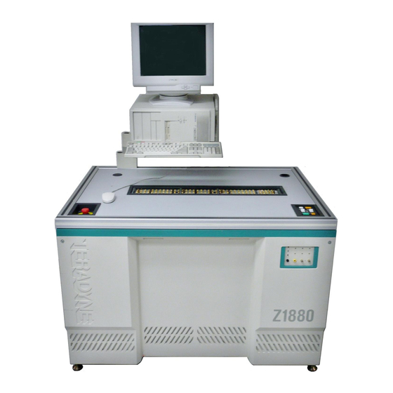
Page 55: Z1890, Z1880
TESTER DESCRIPTION Z1890, Z1880 The Z1890 and Z1880 electronics are housed in one console. Z1890 and Z1880—Front, Top, Right Side (Optional) Vacuum Port 2 Fixture Receiver Interface Emergency Test Jack Panel Manual Off CRT Arm Switch Operator Control Panel Vacuum Port 1 Z1890 and Z1880—Rear and Left Side View... -
Page 56: Z1888—Z1888-1, Z1888-2
Z1888—Z1888-1, The Z1888 electronics are housed in one console and one external line conditioner. The Z1888-2 system is configured as either: • Z1888-1, one test head cage, 1024 pin capacity in a 1-well fixture receiver interface • Z1888-2, two test head cages, 2048 pin capacity in a 2-well fixture receiver interface Z1888—Front, Top, Right Side Emergency (Optional) Vacuum Port 2... -
Page 57: Z1884
TESTER DESCRIPTION Z1884 The Z1884 is divided into a test head bay and a separate power supply bay to accommodate special production line configuration needs. The tabletop extension is standard. Z1884—Front, Top, and Right Side View Tabletop Fixture Receiver Extension Test Jack Panel Operator Control Panel CRT Arm... -
Page 58: Z1866
Z1866 The Z1866 tester is divided into a test head bay and a power supply bay. Z1866—Front, Top, and Right Side View Dual Operator Control Panel Second Vacuum Port Fixture Receiver Test Head Bay Test Jack Panels Vacuum Port Power Supply Bay Stabilizing Feet Door Locks Z1866—Rear and Left Side View... -
Page 59: Z1860-Nb
TESTER DESCRIPTION Z1860-NB The Z1860-NB tester is divided into a test head bay and a power supply bay. Z1860-NB—Front, Top, and Right Side View Operator Control Panel Optional Vacuum Port Test Jack Panel Test Head Bay Fixture Receiver Vacuum Port DUT &... -
Page 60: Z1860
Z1860 The Z1860 tester is divided into a test head bay and a power supply bay. The power supply bay may be moved from the right end to the left end of the test head bay to accommodate production line requirements. The tabletop extension is an option. Z1860—Front, Top, and Right Side View Operator Control Panel Optional Vacuum Port... -
Page 61: Z1850
TESTER DESCRIPTION Z1850 The Z1850 electronics are housed in one console. The tabletop extension is an option. Z1850—Front, Top, and Right Side View Operator Control Panel Optional Vacuum Port Fixture Receiver Test Jack Panel Vacuum Port Z1850 Table Top Extension Stabilizing Feet Z1850—Rear and Left Side View 120V... -
Page 62: Z1840
Z1840 The Z1840 tester is divided into a test head bay and a power supply bay. The power supply bay may be moved from the right end to the left end of the test head bay to accommodate production line requirements. Z1840—Front, Top, and Right Side View Operator Control Panel Optional Vacuum Port... -
Page 63: Z1820
2-10 TESTER DESCRIPTION Z1820 Z1820 electronics are housed in one console. Z1820—Front, Top, and Right Side View Operator Control Panel Vacuum Port Fixture Receiver Vacuum Port T HE PO WE DU T PO WE PO WE CO M OP TIO DU T DU T +18 V... -
Page 64: Z1808, Z1805
2-11 Z1808, Z1805 The Z1808 and Z1805 electronics are housed in one cabinet. Z1808 and Z1805—Front, Top, and Right Side View (Optional) Vacuum Port 2 Fixture Receiver Interface Emergency Test Jack Panel Manual Off CRT Arm Switch Operator Control Panel Vacuum Port 1 Z1808 and Z1805—Rear and Left Side View AC Power... -
Page 65: Z1803 Plus—Z1803-1, Z1803-2
2-12 TESTER DESCRIPTION Z1803 Plus—Z1803-1, The Z1803 Plus system is configured as either: Z1803-2 • Z1803-1, one test head cage, 1024 pin capacity in a 1-well fixture receiver interface • Z1803-2, two test head cages, 2048 pin capacity in a 2-well fixture receiver interface Z1803 Plus—Front, Top, Right Side (Optional) Vacuum Port 2 Fixture Receiver Interface... -
Page 66: Z1800
2-13 Z1800 Z1800 electronics are housed in one console. Z1800—Front, Top, and Right Side View Operator Control Panel Vacuum Port Fixture Receiver Vacuum Port Stabilizing Feet Test Jack Panel Door Locks Z1800—Rear and Left Side View Stabilizing Feet Door Locks Rear Panel Z1800-Series Operator’s Guide... -
Page 67: Z1860M
2-14 TESTER DESCRIPTION Z1860M The Z1860M tester is divided into a test head bay and a power supply bay. The power supply bay may be moved from the right end to the left end of the test head bay to accommodate production line requirements. -
Page 68: Z1850M
2-15 Z1850M The Z1850M electronics are housed in one console. Z1850M—Front, Top, and Right Side View Operator Control Pod Test Jack Panel Stabilizing Feet Z1850M—Rear and Left Side View 120V 50/60 T .16A INPU T PWR WRIS STRA 120V 50/60 AC Power Door Locks Distribution Assembly... -
Page 69: Z1840M
2-16 TESTER DESCRIPTION Z1840M The Z1840M tester is divided into a test head bay and a power supply bay. The power supply bay may be moved from the right end to the left end of the test head bay to accommodate production line requirements. -
Page 70: Console Controls
The operator control panel is mounted on the front right of the test head bay tabletop. The Power Control, Interface Vacuum, Start, and Cancel switches are illuminated when test head power is on. Operator Control Panel—Z1890, Z1888, Z1884, Z1880, Z1860-NB, Z1860, Z1850, Z1840, Z1808, Z1805, Z1803 Plus INTERFACE... - Page 71 2-18 TESTER DESCRIPTION Dual Operator Control Panel—Z1866 The dual operator control panel is mounted on the front right of the test head bay tabletop. The Power Control, Interface Vacuum, Start, and Cancel switches are illuminated when test head power is on. INTERFACE POWER VACUUM...
- Page 72 2-19 Operator Control Panel—Z1820, Z1800 The operator control panel is mounted on the console tabletop. The five push button switches are Start and Cancel and the three vacuum control switches, Manual, Fix 1 (fixture 1) and Fix 2 (fixture 2). The Start and Cancel switches are always illuminated when test head power is on.
-
Page 73: Operator Control Pod
Cancel Terminates a board test. Emergency Manual Off Z1890, Z1888, Z1884, Z1880, Z1808, Z1805 The Emergency Manual Off (EMO) switch is Switch a large red button set in a black panel at the left front corner of the tester’s tabletop. -
Page 74: Test Jack Panels
2-21 Test Jack Panels Test Jack Panel—Z1890, Z1888, Z1880, Z1808, Z1805, Z1803 Plus The test jack panel, located on the front panel, contains 10 jacks and 3 LED indicators. The jacks connect operating and grounding cables and debugging probes to the tester. The LEDs indicate that certain functions are in use. - Page 75 2-22 TESTER DESCRIPTION Test Jack Panel—Z1884, Z1866, Z1860-NB, Z1860, Z1850, Z1840, Z1860M, Z1850M, and Z1840M The test jack panel, located on the front edge of the tabletop or tabletop extension, contains 10 jacks and 3 LED indicators. The jacks connect operating and grounding cables and debugging probes to the tester.
- Page 76 2-23 Test Jack Panel—Z1820, Z1800 The test jack panel, located on the upper right side of the tester console, contains the Power Control switch, 11 jacks, and two LED indicators. The Power Control switch turns on power to the tester and is always illuminated when power is on. The jacks provide connections for operating and grounding cables and debugging probes.
-
Page 77: Interface Vacuum Switches
2-24 TESTER DESCRIPTION Interface Vacuum Interface Vacuum Switch—Z1820 Switches The Interface Vacuum switch, located in a well adjacent to the fixture receiver interface, controls the application of vacuum to the fixture. In the On position, it pulls the fixture onto the tester’s fixture interface. - Page 78 2-25 Interface Vacuum Switch—Z1800 The Interface Vacuum switch, located in a well adjacent to the fixture receiver interface, controls the application of vacuum to the fixture. In the On position, it pulls the fixture onto the tester’s fixture interface. The Interface Vacuum switch for the Z1800 is mechanical. Fixture Receiver Interface Vacuum Switch Z1800-Series Operator’s Guide...
-
Page 79: Rear Panels
TESTER DESCRIPTION Rear Panels Rear Panels—Z1890, The rear of Z1890, Z1888, Z1880, Z1808, Z1805, and Z1805 Plus testers have an AC Z1888, Z1880, Z1808, power distribution assembly, a rear access panel, and a rear (I/O) panel. The AC power Z1805, Z1803 Plus distribution assembly is discussed in the next section of this chapter. -
Page 80: Rear Panel-Z1884, Z1860-Nb, Z1860, Z1840, Z1866, Z1850
2-27 Rear Panel—Z1884, The Z1884, Z1860-NB, Z1860, and Z1840 testers have a panel on the lower left rear of the Z1860-NB, Z1860, test head bay. The test head bay rear panel contains the computer input, the remote port, the Z1840, Z1866, Z1850 wrist strap receptacle, and ground. -
Page 81: Rear Panels-Z1820, Z1800
2-28 TESTER DESCRIPTION Rear Panels—Z1820, Z1820 and Z1800 testers have a rear panel on the lower left rear of the tester which Z1800 contains the computer input, two circuit breakers, the main AC power input, the start pad connector, a wrist strap connector, ground stud, the vacuum inlet, and two 120 VAC outlets which can provide up to 5A. -
Page 82: Ac Power System
AC power cord from the tester to the line conditioner is 15 feet long. The AC power cord coming out of the line conditioner to AC Mains is another 15 feet. The AC power cords for the Z1890, Z1888, Z1880, Z1860-NB, Z1808, Z1805, and Z1803 Plus are not detachable. -
Page 83: Ac Power Distribution Assembly-Z1890, Z1888
2-30 TESTER DESCRIPTION AC Power Distribution The AC power distribution assembly for the Z1890, Z1888, Z1880, Z1808, Z1805, and Assembly—Z1890, Z1803 Plus testers contains power line monitoring circuitry which ensures that acceptable Z1888, Z1880, Z1860- electrical voltages are maintained within the system. -
Page 84: Ac Power Distribution Assembly-Z1884
2-31 AC Power Distribution The AC power distribution assembly for Z1884 contains power line monitoring circuitry Assembly—Z1884 which ensures that acceptable electrical voltages are maintained within the system. The LEDs are not safety indicators. Important: 120V 50/60HZ T .16A 25V 120V 50/60HZ Item #... -
Page 85: Ac Power Distribution Assembly-Z1866, Z1860, Z1850, Z1840,Z1860M, Z1850M, Z1840M
2-32 TESTER DESCRIPTION AC Power Distribution The AC power distribution assembly for the Z1866, Z1860, Z1850, Z1840, Z1860M, Assembly—Z1866, Z1850M, and Z1840M testers contains power line monitoring circuitry which ensures that Z1860, Z1850, Z1840, acceptable electrical voltages are maintained within the system. Z1860M, Z1850M, Z1840M Important:... -
Page 86: Fixture Receiver Interface
Interface provides the interface between the tester and the board test fixture. Fixture Receiver Z1890, Z1888, Z1880-2, Z1808-2, Z1805-2, and Z1803-2 testers have 2048 prewired pins Interface—Z1890, that connect to the driver/receiver boards through the receiver interface. The Z1880-1, Z1888, Z1880, Z1808, Z1808-1, Z1805-1, and Z1803-1 testers have 1024 prewired pins. -
Page 87: Fixture Receiver Interface-Z1884
2-34 TESTER DESCRIPTION Fixture Receiver The Z1884 has 5120 prewired pins that connect to the driver/receiver boards through the Interface—Z1884 receiver interface. Each point has stimulus, measurement, and guarding capabilities for analog and digital testing. Additional interface pins are provided for DUT power supplies, relay array connections, grounds, and other auxiliary features. - Page 88 2-35 Fixture Receiver The Z1866 has two sets of 1024 prewired pins for a total of 2048 pins that connect to the Interface—Z1866 driver/receiver boards through the receiver interface. Each point has stimulus, measurement, and guarding capabilities for analog and digital testing. Additional interface pins are provided for DUT power supplies, relay array connections, grounds, and other auxiliary features.
-
Page 89: Fixture Receiver Interface-Z1866
2-36 TESTER DESCRIPTION Fixture Receiver The Z1860-NB and Z1860 have 2048 prewired pins that connect to the driver/receiver Interface—Z1860-NB, boards through the receiver interface. Each point has stimulus, measurement, and guarding Z1860 capabilities for analog and digital testing. Additional interface pins are provided for DUT power supplies, relay array connections, grounds, and other auxiliary features. -
Page 90: Fixture Receiver Interface—Z1850
2-37 Fixture Receiver The Z1850 has 1024 prewired pins that connect to the driver/receiver boards through the Interface—Z1850 receiver interface. Each point has stimulus, measurement, and guarding capabilities for analog and digital testing. Additional interface pins are provided for DUT power supplies, relay array connections, grounds, and other auxiliary features. -
Page 91: Fixture Receiver Interface—Z1820
2-38 TESTER DESCRIPTION Fixture Receiver The Z1820 has 2048 prewired pins that connect to the driver/receiver boards through the Interface—Z1820 receiver interface. Each point has stimulus, measurement, and guarding capabilities for analog and digital testing. Additional interface pins are provided for DUT power supplies, relay array connections, grounds, and other auxiliary features. -
Page 92: Vacuum System-Vacuum Testers
• WaveScan fixture, which allows you to use a radio frequency stimulus technique to deliver high fault coverage over a range of device types and fault classes. The second vacuum valve is standard for the Z1890, Z1884, and Z1866, but it is an Important: option for the other Z1800-Series testers, and must be installed to use the tandem fixture. - Page 93 2-40 TESTER DESCRIPTION...
-
Page 94: Operating The Tester
HAPTER PERATING THE ESTER Default permissions for operators are limited to logging in, selecting a test, and running a test. The procedures in this chapter are based upon these defaults. For detailed explanations of the Z1800-Series software, see the Z1800-Series Programmer's Guidebook. -
Page 95: Daily Operations
OPERATING THE TESTER Daily Operations Because Teradyne recommends that you keep the tester power on except for maintenance and emergencies, daily operations do not include powering the tester on and off. For information about those procedures see the “Power On/Off Sequence” section in Chapter 1 of this manual. -
Page 96: Check The Printer
Z1800-Series manuals are bound in static-dissipative binders. They will not store an Note: electrostatic charge and are safe to use near sensitive electronic components. Teradyne recommends against making copies of pages for use around testers—photocopies may carry electrostatic charges. -
Page 97: Board Testing
• Testing boards • Analyzing test printout results Load the Fixture and Load the Board and Fixture for the Z1890, Z1888, Z1884, Z1880, Z1860-NB Board MS, Z1860, Z1850, Z1840, Z1820, Z1808, Z1805, Z1803 Plus, Z1800 Refer to the illustration below as you read this procedure. -
Page 98: Login
Press the Vacuum Interface switch to pull the fixture on to the fixture receiver interface. Connect the vacuum hose(s) to the fixture hose fitting(s). Set the fixture vacuum switches on as required. Set the operator control panel for Tandem or Independent. In Tandem mode, the Start and Cancel of either system affect both systems. -
Page 99: Test Boards
OPERATING THE TESTER The User Login window appears. Operator will be preselected in the User Login window. User Login Login Operator Password Cancel Select new Login name. Select the Password field and type your password. Move the cursor to the OK field using the mouse or arrow keys. Select OK. - Page 100 18xx Windows mode Files Edit Run Pgen Setup Utility Templates GFI Convert Press START to test a board Option 1 Option 2 Option 3 Option 4 Option 5 Option 6 Option 7 C:\TPD\DEMO.DCA-ICT START CANCEL SOF HLD RPT CRT ICT or FST Indicator Select Program Name Selecting Option Buttons By displaying messages in the CRT Output window, the test...
- Page 101 OPERATING THE TESTER Toggle the Test Control buttons to select or deselect a function. You can toggle these buttons before the test starts or during test execution. To toggle the buttons, either point the mouse cursor at the button on the screen and click, or press the appropriate function key as described by the keyboard template.
- Page 102 no next step, pressing the Start key when repeating the last measurement of a component turns Repeat off. The Repeat button does not function with shorts or ignores. • Cathode Ray Tube (CRT) When CRT is on, program progress information is displayed on the CRT. One line of information is displayed per test step.
- Page 103 3-10 OPERATING THE TESTER Follow the steps below to select the program. Select the Test Program Choose Select from the Files menu. A list of available programs appears in the Select window. Select the program to execute. The selected program name appears at the bottom of the screen, followed by either ICT to indicate in-circuit test or FST to indicate fixture-self test.
-
Page 104: Testing Digital Connectivity
3-11 Testing Digital Digital Tracer is a digital testing tool which allows you to test the connectivity of digital Connectivity component leads to the board-under-test via a hand held probe. Once Digital Tracer has been enabled in the software, it stops a test when it locates a failing device and shows a representation of the device on the screen. - Page 105 3-12 OPERATING THE TESTER The pin contact indicator shows when the probe has made contact Pin Contact Indicator with a target pin. Target pins are pins that the operator has not yet probed. When the probe contacts the pin, the pin contact indicator changes color and Digital Tracer makes a beep. Digital Tracer cannot individually display all the pins for high density devices;...
- Page 106 3-13 A legend on the upper right hand corner of the screen describes keyboard usage Legend and is valid only during orient mode. During orient mode, you can manually override the device orientation and type from the keyboard if the programmer has not correctly oriented the device in the setup.
- Page 107 3-14 OPERATING THE TESTER The pin number indicator at the lower right hand corner of the Pin Number Indicator screen specifies the actual number of pins represented on each side of the device. Files Edit Pgen Setup Utiility Templates Convert [ ]—[ ] Tracer——cancel to terminate Pin contact...
- Page 108 3-15 <ID> and <NAME> are replaced with component data. Important: If the programmer has not correctly oriented the device in the setup, you can manually override the orientation and device type. Use the keyboard to change the package and orientation. Once you start probing, you cannot change the display.
- Page 109 3-16 OPERATING THE TESTER • Top—Increase or Decrease Pins To decrease the number of pins on the top and bottom of a Quad device and redistribute the pins to the sides, press the < key. To increase the number of pins on the top and bottom of a Quad device and redistribute the pins to the sides, press the >...
-
Page 110: Analyzing Printout Of Test Results
3-17 After the initial pass, if Tracer Second-Pass is enabled in Probing Tied Pins Individually the header, Digital Tracer prompts you to probe the tied pins a second time, separately, to determine if the trace between them is broken. A message window appears, instructing you which pins to probe. "Tracer - Pin Check Utility Please probe pin <n>... -
Page 111: Autoprobecheck Failure Messages
3-18 OPERATING THE TESTER Capacitor failure C4 100nF 100 nanofarad 50 nF NODE 90 PIN: Resistor failure R28 10kΩ 10 kilohms 8 KO NODE 67 PIN: Resistor Pack failure RP1 22.00K0 22.00 kilohms 20.8 KO NODE 66 PIN: 18.6 KO NODE 35 PIN: 24.3 KO... -
Page 112: Shorts Locator Messages
3-19 Section Abort Section Abort is a function enabled in the program Header. When it is on, Section Abort Messages stops the program execution if failures are encountered early in the test. Failures in early sections can produce false readings in subsequent sections, or, in the case of a short, could result in damage to the board if DUT power is turned on. -
Page 113: Troubleshooting For Operators
Solution: • Turn the Power Control switch off and on. For the Z1890, Z1884, Z1880, Z1866, Z1860-NB MS, Z1860, Z1850, Z1840, Z1808, and Z1805: the Power Control switch is on the operator control panel. For the Z1820 and Z1800: the Power Control switch is on the test jack panel. -
Page 114: Run Command
• Check that your computer/tester cable is connected correctly and that tester power is on. • Return to the Main menu to reselect Program Test Run. Vacuum Tester The problems described below may occur when you are using Z1890, Z1884, Z1880, Problems Z1866, Z1860-NB MS, Z1860, Z1850, Z1840, Z1820, Z1808, Z1805, and Z1800 testers. - Page 115 3-22 OPERATING THE TESTER...
- Page 116 NDEX AC power distribution assembly 2-30 2-31 2-32 failure messages 3-17 3-18 3-19 accessing internal parts safely fixture inspection, daily AutoProbeCheck (APC) 3-18 fixture receiver interface 2-33 2-34 2-35 2-36 2-37 fixture, loading onto tester board failures fixtures for vacuum testers 2-39 entire batches 3-20...
- Page 117 2-39 Interface Vacuum 2-24 2-25 operator control panel 2-17 2-18 2-19 operator control pod 2-20 wrist strap Power Control symbols, safety temperature range for safe operation Teradyne Product Safety Standards test controls Cathode Ray Tube (CRT) Hold (HLD)
- Page 118 Artisan Technology Group is your source for quality new and certified-used/pre-owned equipment SERVICE CENTER REPAIRS WE BUY USED EQUIPMENT • FAST SHIPPING AND DELIVERY Experienced engineers and technicians on staff Sell your excess, underutilized, and idle used equipment at our full-service, in-house repair center We also offer credit for buy-backs and trade-ins •...
Need help?
Do you have a question about the Z1880 and is the answer not in the manual?
Questions and answers