Table of Contents
Advertisement
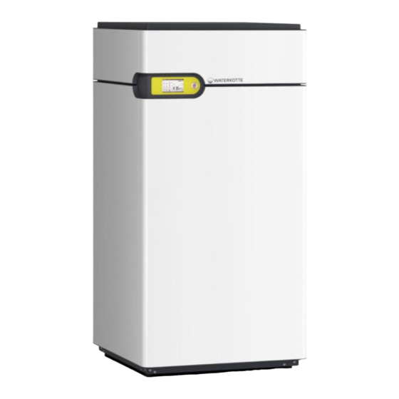
Planning and installation
EcoTouch DS 5050T
2-power levels (0 % - 50 % - 100 %)
WATERKOTTE GmbH, Gewerkenstraße 15, D-44628 Herne
Tel.: 0049/(0)2323/9376-0, Service: 0049/(0)2323/9376-350
Fax: 0049/(0)2323/9376-99, E-Mail: info@waterkotte.de
Internet: http://www.waterkotte.de
Z18494 / 20092012
04.12..2015 / Z21974
Advertisement
Table of Contents

Related Manuals for WATERKOTTE EcoTouch DS 5034.5T


Summary of Contents for WATERKOTTE EcoTouch DS 5034.5T
- Page 1 Planning and installation EcoTouch DS 5050T 2-power levels (0 % - 50 % - 100 %) WATERKOTTE GmbH, Gewerkenstraße 15, D-44628 Herne Tel.: 0049/(0)2323/9376-0, Service: 0049/(0)2323/9376-350 Fax: 0049/(0)2323/9376-99, E-Mail: info@waterkotte.de Internet: http://www.waterkotte.de Z18494 / 20092012 04.12..2015 / Z21974...
- Page 2 This publication has been prepared with all reasonable care. WATERKOTTE GmbH does not assume any liability for remaining errors or omissions, or for possible damages. 2 / 48 04.12.2015...
-
Page 3: Table Of Contents
Overview (unit opened) ....................12 Components and installation ....................13 Heating system EcoTouch DS 5050T ................13 Installation........................13 4.2.1 Heat pump system series EcoTouch DS 5050T ..........13 4.2.2 Heat pump module .................... 13 Electrical equipment ....................... 14 4.3.1 Electronic heat pump control ................ - Page 4 14.5 Heat pump EcoTouch DS5050T ground water or ground – with connection accessory F10815 (option) ..................... 42 14.6 Description of the parts in the connection diagram ............43 Technical data ......................... 45 4 / 48 04.12.2015 Copyright 2014 by: WATERKOTTE GmbH. Subject to changes.
- Page 5 Do not release R410A into the atmosphere: R410A is a fluorinated greenhouse gas according to Kyoto Protocol and has a global warming potential (GWP) of 1600. 5 / 48 04.12.2015 Copyright 2014 by: WATERKOTTE GmbH. Subject to changes.
-
Page 6: Safety
Safety 1 Safety 1.1 Intended use Your WATERKOTTE heat pump is used for space heating and cooling, and heating of domestic water. Project planning of the heat source system must be performed in compli- ance with the technical information provided by WATERKOTTE for layout of heat source systems. -
Page 7: Environmental Protection
Parts and special equipment not delivered by WATERKOTTE are not ap- proved for use on the heat pump. 1.3 Hazards... - Page 8 In case of heat pump failure, before restart an inspection by qualified and authorised personnel must be performed. Due to test bench operation, the heat pump can have ethylene glycol resi- dues. 8 / 48 04.12.2015 Copyright 2014 by: WATERKOTTE GmbH. Subject to changes.
-
Page 9: Specific Types Of Hazards
Switch off unit and allow to cool down. 1.5 Operator's duty of care Your WATERKOTTE heat pump has been designed and built on the basis of a risk analysis and after careful selection of standards to be observed. Thus, your heat pump is state-of-the-art and provides for maximum safety. -
Page 10: Functional Principle Of Heat Pump
heating system EcoTouch DS 5050T domestic hot water tank Driving energy Heat source Energy output Low temperature Heat pump Figure 1: Energy share when using a geothermal energy pump 10 / 48 04.12.2015 Copyright 2014 by: WATERKOTTE GmbH. Subject to changes. -
Page 11: Product Description
Product description 3 Product description 3.1 Overview Figure 2: Heating system EcoTouch DS 5050T ON / OFF switch Control panel (electronic heat pump controller) 11 / 48 04.12.2015 Copyright 2014 by: WATERKOTTE GmbH. Subject to changes. -
Page 12: Overview (Unit Opened)
Product description 3.2 Overview (unit opened) Illustration 3: EcoTouch DS 5050T (top view, opened Safety group with manometer: relief valve, bleeder Connection terminal 12 / 48 04.12.2015 Copyright 2014 by: WATERKOTTE GmbH. Subject to changes. -
Page 13: Components And Installation
Manufacturing quality is carried out based on ISO 9000ff, supple- mented by an automated computer-monitored quality test (pressure stress and helium leak test) in addition to inspection of all parameters in a subse- quent trial run. 13 / 48 04.12.2015 Copyright 2014 by: WATERKOTTE GmbH. Subject to changes. -
Page 14: Electrical Equipment
The heat pump control (control panel is pictured) is included in the scope of delivery of the WATERKOTTE heat pump. Use in other than WATERKOTTE heat pumps will void any warranty claim. The control is used to control and monitor heating systems that are operat- ed with WATERKOTTE compact heat pumps according to technical guide- lines of WATERKOTTE Wärmepumpen GmbH. -
Page 15: Transport
Please also read chapter "General safety information“. 5.1 Transport to installation site Units of the EcoTouch DS 5050T series are delivered ready-to-connect with separate metal cladding. For transport purposes, the metal cladding and the heat pump are delivered in one carton on a palette. During transport it must be ensured that appropriate means of transport are used (lift truck, transport rollers, handcart). -
Page 16: Installation
10 mm thick rubber mat. Acoustics in in- stallation rooms with rigid walls can noticeably increase operating noise. Counter measure: acoustic insulation of one of the opposite wall or ceiling surfaces. 16 / 48 04.12.2015 Copyright 2014 by: WATERKOTTE GmbH. Subject to changes. -
Page 17: Creating The Foundation And Installing Heat Pump
Insulation material (3 layer, polyurethan rubber) Supporting subsurface Insulation material Screed Concrete plinth Dimensions concrete plinth (mm): Plinth Width Depth High EcoTouch 850 mm 700 mm 150 mm DS 5050T 17 / 48 04.12.2015 Copyright 2014 by: WATERKOTTE GmbH. Subject to changes. -
Page 18: Installation Of The Housing
So you can’t damage the retaining bolts (see Figure). The removal tool is driven with moderate force, by hand, into the gap between the front and side panel. 18 / 48 04.12.2015 Copyright 2014 by: WATERKOTTE GmbH. Subject to changes. -
Page 19: Installation And Connection
7 Installation and connection 7.1 Connections EcoTouch DS 5050T (rear side) Figure 4: Connections EcoTouch DS 5050T heating and heat source( 2“ flat sealing) 7.2 Connection to heating system The connected systems should be technically clean and free from air. Steel pipes and other steel components in the water circuit shall not be used when connecting diffusion-open surface heating system. -
Page 20: Heat Pump With Underfloor Heating
The heat pump control regulates the temperature of the buffer tank. After the tank, the components (circulation pump, mixing valve ...) must be controlled with an optional WATERKOTTE mixing control (P11108). If the formation of deposits is to be expected (e.g. strong contamination) based on water quality, cleaning must be performed in regular intervals. -
Page 21: Heat Pump With Swimming Pool
PE-pipe 20x2) or a vertical geothermal absorber (geothermal probes). The groundwater: by connection to a well system, using an accessories kit available from WATERKOTTE to monitor the flow at heat source side and separation heat exchanger (heat source side). - Page 22 Tel. : (+49) (0) 23 23 / 9 37 60 10000 Permitted chloride contend depending on the temperature No working area Working area without any problems 1000 Not used Usable without problems Temperature [°C] 22 / 48 04.12.2015 Copyright 2014 by: WATERKOTTE GmbH. Subject to changes.
-
Page 23: Flow Monitoring
The volume flow has to be increased at a lower inlet temperature (< 10 °C). The outlet temperature of the heat pump should not fall below a value of 4 °C ! 23 / 48 04.12.2015 Copyright 2014 by: WATERKOTTE GmbH. Subject to changes. -
Page 24: Groundwater Installation: Separating Heat Exchanger
The intermediate circuit has to be filled with ca. 15 % Ethylene-Glycol. Z 2 0 Under floor heating Heat pump Heat source Expansion tank Safety fitting Heat exchanger (Ground water/Ethylene-Glycol 15 %) Dirt trap (0.8 mm mesh width) 24 / 48 04.12.2015 Copyright 2014 by: WATERKOTTE GmbH. Subject to changes. -
Page 25: Electrical Work
All connections performed directly at the plug connections of the relay circuit board must be established with flexible lines; if necessary, inter- mediate terminals must be used. 25 / 48 04.12.2015 Copyright 2014 by: WATERKOTTE GmbH. Subject to changes. -
Page 26: Installation Instructions For External Sensor
The cable for the electric wiring can be passed through the openings to the upper rear wall of the heat pump. The cables are fixed by means of strain relief and cable glands. 26 / 48 04.12.2015 Copyright 2014 by: WATERKOTTE GmbH. Subject to changes. -
Page 27: Electrical Connections
Electrical work 8.4 Electrical connections 27 / 48 04.12.2015 Copyright 2014 by: WATERKOTTE GmbH. Subject to changes. -
Page 28: Controller Wwpr 2
NO11 – Multifunctional exit NO11 – Sortie multifonction NO12 – Stetiges Kühlsignal NO12 – Continuous cooling signal NO12 – Signal rafraîchissement cons- tant NO13 – NO13 – NO13 – 28 / 48 04.12.2015 Copyright 2014 by: WATERKOTTE GmbH. Subject to changes. -
Page 29: Connectors
Electrical work 8.6 Connectors 29 / 48 04.12.2015 Copyright 2014 by: WATERKOTTE GmbH. Subject to changes. -
Page 30: Pipe & Instrumentation / Measurement & Control Technology
2 Part Design Compressor full hermetic scroll Condenser steel plate pack, copper soldered Filter dryer Refrigerant inspection glass Expansion valve electronic Evaporator steel plate pack, copper soldered 30 / 48 04.12.2015 Copyright 2014 by: WATERKOTTE GmbH. Subject to changes. -
Page 31: Commissioning
Components that are rotating, hot or under high voltage can cause injuries. Warning! Risc of electric shock! Do not touch switch with wet hands. This poses a risk of electric shock. 31 / 48 04.12.2015 Copyright 2014 by: WATERKOTTE GmbH. Subject to changes. -
Page 32: Initial Start-Up Of Machine
Figure 1: ON / OFF switch (see pointing arrow) Switch lights => Power on (normal operation)) The initial start of the heat pump is performed by a qualified WATERKOTTE system partner. After all checks have been conducted, proceed as follows: 1. -
Page 33: Control Of Entire Operation
Tip: The correct use of the controller saves money. Particularly the correct settings of flow temperature, hot water temperature, heating curve and heating times can result in substantial cost savings. 33 / 48 04.12.2015 Copyright 2014 by: WATERKOTTE GmbH. Subject to changes. -
Page 34: Turning Heat Pump Off
Main switch of heat pump in OFF position (no light). Turn off LS switch: Compressor, control voltage. 10.5 Taking heat pump out of operation for extended period - see 10.4 . 34 / 48 04.12.2015 Copyright 2014 by: WATERKOTTE GmbH. Subject to changes. -
Page 35: Troubleshooting
Overheating of motor winding; possible causes: Failure of a phase, me- chanical failure due to lack of lubrication, lack of refrigerant, defects in refrigerant regulation, operation with incorrect refrigerant, excessive temperature of pressurised gas. 35 / 48 04.12.2015 Copyright 2014 by: WATERKOTTE GmbH. Subject to changes. -
Page 36: Safety Measures
12.3 Refrigerator oil Use only the specified oil type (ester oil ICI Emkarate RL 32-3MAF); non- compliance will result in exclusion of warranty and certainly cause malfunc- tions. 36 / 48 04.12.2015 Copyright 2014 by: WATERKOTTE GmbH. Subject to changes. -
Page 37: Maintenance And Care
Check control settings. Leakage test: The statutory inspection intervals depending on the re- frigerant volume. details, see the heat pump logbook 37 / 48 04.12.2015 Copyright 2014 by: WATERKOTTE GmbH. Subject to changes. -
Page 38: Connection Diagrams
Connection diagrams 14 Connection diagrams 14.1 Heat pump EcoTouch DS5050T with underfloor heating system, without single room control 38 / 48 04.12.2015 Copyright 2014 by: WATERKOTTE GmbH. Subject to changes. -
Page 39: Heat Pump Ecotouch Ds5050T With Underfloor Heating System And Single Room Control
Connection diagrams 14.2 Heat pump EcoTouch DS5050T with underfloor heating system and single room control 39 / 48 04.12.2015 Copyright 2014 by: WATERKOTTE GmbH. Subject to changes. -
Page 40: Heat Pump Ecotouch Ds5050T With Underfloor Heating System, Without Single Room Control, With Hygienic Hot Water Heating
Connection diagrams 14.3 Heat pump EcoTouch DS5050T with underfloor heating system, without single room control, with hygienic hot water heating 40 / 48 04.12.2015 Copyright 2014 by: WATERKOTTE GmbH. Subject to changes. -
Page 41: Heat Pump Ecotouch Ds5050T Ground Water Or Ground - With Connection Accessory F10815 (Option)
Connection diagrams 14.4 Heat pump EcoTouch DS5050T ground water or ground – with connection ac- cessory F10815 (option) 41 / 48 04.12.2015 Copyright 2014 by: WATERKOTTE GmbH. Subject to changes. -
Page 42: Heat Pump Ecotouch Ds5050T Ground Water Or Ground - With Connection Accessory F10815 (Option)
Connection diagrams 14.5 Heat pump EcoTouch DS5050T ground water or ground – with connection ac- cessory F10815 (option) 42 / 48 04.12.2015 Copyright 2014 by: WATERKOTTE GmbH. Subject to changes. -
Page 43: Description Of The Parts In The Connection Diagram
(heating and cooling) 2nd heat generator non-return valve regulating valve dirt trap motor-powered switch valve 43 / 48 04.12.2015 Copyright 2014 by: WATERKOTTE GmbH. Subject to changes. - Page 44 (swimming pool) multiple-ply filter for pool water cleaning pool water - disinfection system ph – value control- and adjustment system pool water – drain pool water circulation pump 44 / 48 04.12.2015 Copyright 2014 by: WATERKOTTE GmbH. Subject to changes.
-
Page 45: Technical Data
Heat source (70 % water + 30 % ethylene glycol). . When the composite label Waterkotte WWPR controller class III was considered (without room temperature sensor). 45 / 48 04.12.2015 Copyright 2014 by: WATERKOTTE GmbH. Subject to changes. - Page 46 Technical data 46 / 48 04.12.2015 Copyright 2014 by: WATERKOTTE GmbH. Subject to changes.
- Page 47 Technical data 47 / 48 04.12.2015 Copyright 2014 by: WATERKOTTE GmbH. Subject to changes.
- Page 48 Technical data WATERKOTTE GmbH, Gewerkenstraße 15, D-44628 Herne Tel.: 0049/(0)2323/9376-0, Fax: 0049/(0)2323/9376-99 Service: 0049/(0)2323/9376-350 E-Mail: info@waterkotte.de, Internet: http://www.waterkotte.de 48 / 48 04.12.2015 Copyright 2014 by: WATERKOTTE GmbH. Subject to changes.
Need help?
Do you have a question about the EcoTouch DS 5034.5T and is the answer not in the manual?
Questions and answers