Table of Contents
Advertisement
Quick Links
Advertisement
Table of Contents

Related Manuals for Seacraft ENC2


Summary of Contents for Seacraft ENC2
- Page 2 Marine Tech accepts no liability for damages and/or injuries caused by improper use of the Seacraft ENC2 as well as a result of its use in a manner contrary to or deviating from principles set out in this manual.
- Page 3 Should you have any questions or comments regarding this manual, please contact: Manufacturer: MARINE TECH SA ul. Żwirki i Wigury 1 7 38-400 Krosno , Poland Email: info@seacraft.eu Web: www.seacraft.eu Document Information: Title: Quick User Guide Seacraft ENC2 Document Version: 1 .3 Software Version: 1 .5 Publication Date: 26.06.201 9...
-
Page 4: Table Of Contents
Table of Contents Technical specifications ......................6 P recautions ..........................7 M echanical construction ......................8 C ontrol ............................. 9 M ain screen layout ........................11 6. Additional inform ation screen (next to main) ..............16 D estination parameters – setting and chang ing ............20 M EN U screen ........................ - Page 5 20 . U nits ............................4 3 C ompass ..........................4 4 C lear data ..........................4 8 F actory reset ........................4 8 24 . Exit ............................4 8 Auxiliary software for Android - installing ..............4 9 ® Auxiliary software for Windows - installing ...............
-
Page 6: Technical Specifications
1 . Technical specifications Model Power source ENC II Built-in Li-ion 3,7 V battery Type ENC v.2 Battery capacity 5 Wh Maximum depth Typical working time 300 m 20-35 h Tested depth 350 m Average charge time <2 h Depth of start and stop of Optional: 0.5, 1 or 1 .6 m... -
Page 7: Precautions
2. Precautions This manual is suitable for the navigation device with software version 1 .5.1 0 to 1 .5.1 3. The software version number is shown under MENU, when the battery voltage is displayed (OFF option selected). WARNING ! This device may have some bugs in the software, which we did not find yet. You should never risk your life using this device as sole advisor. -
Page 8: Mechanical Construction
3. Mechanical construction Fig. 1 . Description of elements. 1 . Universal mounting – top side 2. Ambient light sensor (do not cover) 3. Additional LED diode (red color) 4. Screen / display 5. Top button (NEXT) 6. Bottom button (SET, REC, HOLD) 7. -
Page 9: Control
4. Control Button functions (depending on actual screen content): Top button (5) – NEXT screen / NEXT item / CANCEL change / BACK Bottom button (6) – SET / change value / enter changing item / switch between REC and HOLD state Note On most screens, a small graphical hint is displayed in top and bottom right corner of the display. - Page 10 First steps - switching on and off: Switching on the device – press both buttons at the same time. The device will also switch on when immersed in water min. 0.3 m (1 ft) deep. Switching off the device – You have to stop recording first. Then go to MENU (from main screen – press the top button 3 times, then press the bottom button once).
-
Page 11: Main Screen Layout
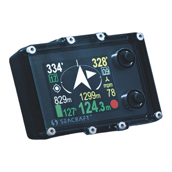
5. Main screen layout After power on, the device display will show this content:... - Page 12 Screen elements: 1 . Course to planned destination. If no destination is Present marker number. For using markers, please see programmed, this field is blank. next chapter. 2. Present memory slot number. If you start recording, Destination direction arrow. The tip of the arrow is always the dive data will be saved in the device memory with pointing to the planned destination.
- Page 13 Battery indicator Icon Charge on % Time left Icon Charge in % Time left 85-1 00 20-25 h 28-45 5-1 0 h 68-84 1 7-20 h 1 2-27 1 -5 h 46-67 1 0-1 7 h 1 -1 1 <1 h Caution: The value ‘Time left’...
- Page 14 Navigation arrow colors: White – Normal operation with or without programmed destination Green – Destination is set and distance to it is less than 1 0 meters Orange – The diver is returning to the start point (distance >1 0 meters) GPS indicator: Icon Meaning...
- Page 15 Depth indicator colors: Color Meaning More info Vertical speed (up or down) is less No special actions required from diver. than 9 m/min (29.5 ft/min) Vertical speed (up or down) is equal There is a noticeable depth change. or greater than 9 m/min (29.5 ft/min) The user should be aware, that ascending or Vertical speed (up or down) is equal descending at this speed may have negative health...
-
Page 16: Additional Information Screen (Next To Main)
6. Additional information screen (next to main) After pressing the top button on the main navigation screen, the display content changes like shown above. On the left side of the screen, all present information are shown. On the right side there is a list with all available options. - Page 17 Note If some of parameters cannot be evaluated, a ‘---‘ value will be shown instead. Buttons role: Top button – Select the NEXT item. After 3 press, you will return to the main navigation screen. Bottom button – ENTER to activate the selected item. Note: If the destination parameters are cleared (not set), this screen looks like this:...
- Page 18 If the RETURN item is selected, the screen looks like below: 1 - The course you need to follow in order to return to the 5 - Top button role – go to next (lower) start point item 2 - The time required to return to the start point (approx.) 6 - Currently selected item 3 - The distance from current location to the start point 7 - Bottom button role –...
- Page 19 If the MENU item is selected, the screen looks like this: 1 - Internal date (DD.MM.YY) 2 - Internal time (hh:mm), in 24-hour system 3 - Water temperature 4 - Operation hint – when you press the lower button, other functions will be shown. 5 - Stopwatch The description regarding the right display side is the same as on previous picture.
-
Page 20: Destination Parameters - Setting And Changing
7. Destination parameters – setting and changing When you activate the DESTIN(ation) option on the additional information screen (see fig. 1 on p. 6), the device will show the current destination parameters (if set) or it will suggest new ones, as shown in the following picture: 1 - Current route number in memory / total routes in memory 2 - Azimuth –... - Page 21 If you press the lower button (ENTER) when azimuth is selected, the display will change like this: You may now rotate the device, in order to set the desired heading. Then simply press the lower button (ENTER), if the value is appropriate. You may also press the upper button now. This will allow you to set the desired azimuth manually digit by digit (use the lower button to change the value).
- Page 22 Next, set the distance – you may do it when the second line is highlighted: Distance value is changed also digit by digit. Pressing the top button switches to the next position, the bottom button changes the value 0 > 1 > 2 > … > 9 > 0. Note The minimal allowed distance is 1 0m (or 0.01 mile).
- Page 23 When both parameters (azimuth and distance) are set, pressing the top button will bring up the command line. You may choose from two commands, using the top button: NAVIGATE – Apply values and switch to main screen (with destination) CLEAR DESTIN(ation) – Clear all values and switch to main screen (without destination) Notes The DESTINATION, once set, is held in memory until cleared or changed (power off will not clear programmed values).
-
Page 24: Menu Screen
8. MENU screen If you press the lower button (ENTER) when the MENU item is highlighted on the additional information screen (see fig. 1 on p. 6), you may choose between 4 commands: OFF – Allows you to switch off the device. The left part of the screen shows information about the present battery charge. - Page 25 GRAPH – Allows you to show the position and depth graphs on the device screen. More info about graphs can be found in chapter 9 and 1 0. On the left side of the screen, the device shows 2 numbers: Current routes in memory / maximum routes in memory.
- Page 26 SETUP – This allows you to show and change all internal configuration parameters. More about this function can be found in chapter 1 2. On the left side on the screen, the most important settings are shown in short form (to avoid unnecessary activation of the configuration just to check it).
-
Page 27: Depth Profile Graph
9. Depth profile graph If you press the lower button (ENTER), when the GRAPH item on the MENU screen is highlighted, you will be redirected to the simple graph browser. The first available graph is called ‘depth profile’ and contains a representation of dive depth vs time, as shown below: 1 - Top button role (now –... -
Page 28: Swim Route G Raph
1 0. Swim route graph This screen presents the changes in the diver location projected on a flat surface (like on a map). The route start point is always positioned in the screen center. The route end point will be shown as a green dot, but only on the present route. Near the right edge of the screen, you will find some information elements: 1 - Top button role (now –... - Page 29 You may tilt the device to the left or to the right, in order to change the button roles on this screen. When tilted left, the lower button brings you to previous route number. When tilted right, the lower button will allow you to delete the current route.
-
Page 30: Tim Er / Stopwatch
1 1 . TIMER / stopwatch If you press the lower button (ENTER) when the TIMER item on the MENU screen is highlighted, you will be redirected to the TIMER/STOPWATCH control screen: 1 - EXIT – current selected command; if you press lower button (ENTER), you will return to main navigation screen 2 - Timer START –... -
Page 31: D Evice Config Uration (Setu P )
1 2. Device configuration (SETUP) If you press the lower button (ENTER) when the SETUP item on the MENU screen is highlighted, you will be redirected to the SETUP menu. Device settings are organized in 2 screens. The selected function is highlighted. The top button (NEXT) will switch the selected function to the next one (below). -
Page 32: Send Data
1 3. Send data Used to activate the internal Bluetooth transmitter. Activate it before any data transmission from the navigation device to a PC or smartphone. When this function is activated, the device will not power off automatically (except when the battery is low). - Page 33 Note If data transfer hangs, you can STOP transmission, wait 2-3 seconds and enter into “Send data” option again. This procedure can also help, if PC or mobile software cannot “see” your ENC2 device. CAUTION – when you updating ENC2 firmware and you have to break this operation, ALWAYS use STOP button on ENC2 device first (before closing program or PC/mobile device).
-
Page 34: P Ressure/Salinity
1 4. Pressure/salinity Shows the current pressure in milibar (green color). 1 PSI ≈ 68,95 milibar. When no pressure is shown, the pressure sensor is defective. The lower line shows the pressure correction (white color) – this value will be added to the raw value of the measured pressure. -
Page 35: L Og /Speed
1 5. Log/speed This navigation console can work with an external sensor (speed sensor) or without it (inertial mode). This option can be used to switch between these two modes. The field ‘Calc. distance from’ may switch between ‘External log’ and ‘Const. speed’. The first value needs an external speed sensor (log) to be connected. - Page 36 If you want to recalibrate the sensor, set the chosen distance in meters (reference distance) by pressing the lower button and changing the value digit by digit. Then, you will be guided to the next item, which shows how many pulses are counted in a distance of 1 00m.
-
Page 37: L Og /Speed Calibration
When ‘Calc. distance from’’ is set to ‘Const. speed’’, a constant average speed is chosen to calculate the position (on the main screen, no log symbol is visible). The option ‘Calibrate’ will allow you to set a constant average speed used to calculate the current position, the return time and the target time. - Page 38 Pulses value can be altered by type of DPV, mounting position, and influence of for example “propeller suction” effect. Devices are calibrated to be used with Seacraft scooters, which construction allows for optimal sensor placement, and minimizes interferences. While for general orientation underwater factory setting will be fine with most types of DPV’s, for more precise applications- as for example mapping- we recommend speed log calibration with whole set-up used.
- Page 39 It is possible to set the calibration factor also without a need to dive and measure a known distance underwater. In case that logged route indicates deviation of covered distance - and currents presence or wrong mounting/ log damage are ��������...
- Page 40 1 7. GPS This menu option is for information purposes only. When selected, the navigation screen will show the GPS status information as described below: Valid: Y/N – Displays, if GPS information is available now Sat.cnt: 0…1 5 – Number of satellites used to calculate the position (more = better) Latt.
-
Page 41: Time/Date
After power on, first GPS readings should be available after 20-60 seconds. The GPS antenna is located between the buttons, so you should not cover this point with any objects. You may tilt the navigation console as far as possible (screen upwards) for a while, to achieve better/quicker GPS readings, but this is not necessary in most cases. -
Page 42: O Ther Setting
1 9. Other settings Miscellaneous other settings are available as a separate screen: Backlight – [1 , 2, 3, 4, 5, auto] – Changes the display backlight intensity. Value 1 means the constant lowest brightness (about 20%), value 5 means the constant maximum brightness (about 95%), value ‘auto’ means that the backlight will be auto adjusted using the ambient light sensor. -
Page 43: Units
20. Units Allows you to choose the units of the values presented on the screen: Temperat.(ure) – Can be °C (Celsius) or °F (Fahrenheit) Depth – Can be meters or feet Speed – Can be m/min (meters per minute) or knots (nautical miles per hour) Distance –... -
Page 44: Compass
21 . Compass Allows to calibrate the magnetometer (compass sensor) and to set the magnetic declination and deviation. Calibration – This option is used for basic magnetometer calibration. You should use this function, when the compass direction shown on this device is improper. This is usually needed when the magnetic properties of the environment have changed. - Page 45 Caution: The new calibration can be worse than the existing. If you are not happy with the results, calibrate the compass again or restore the factory settings. After the basic calibration, you should set declination and deviation to 0 (zero), clear the precision calibration (see below), and set it again. Geometry –...
- Page 46 Current – Raw heading from magnetometer, without correction. Stored – Stored value for this step. The lower button will store the Current value as Stored, each time you press it. The upper button will guide you to the next step. On the last screen you can check, if this calibration improved the heading display. This screen is named ‘Accuracy test’...
- Page 47 If the corrected values are better than the measured values, press the lower button (ENTER) to store the results. If you press the upper button, no changes will be stored. Caution: Beware of placing another compass near this device when performing this calibration, because it might affect the measurement and affects the calibration procedure.
-
Page 48: Clear Data
22. Clear data Clears all records from the internal memory. The user will be asked, if he really wants to perform this operation. It is recommended to power off and on the device after using this feature. 23. Factory reset After using this option, all settings will be restored to factory values, and all other data will be lost. -
Page 49: Auxiliary Software For Android
25. Auxiliary software for Android - installing ® Go to Google Play store, find SEACRAFT application and then install it on your device. In case of any trouble, use this direct link below : https://play.google.com/store/apps/details? id=eu.seacraft.console Minimum requirements for your mobile device : Operating system Google Android 5.0 or newer... -
Page 50: Auxiliary Software For Windows ® - Installing
26. Auxiliary software for Windows - installing ® Go to Microsoft Store, find and install SEACRAFT application. In case of any trouble, use this direct link below : https://www.microsoft.com/store/apps/9PHMWFKJ7NQL ms-windows-store://pdp/? productid=9PHMWFKJ7NQL Minimum requirements for your computer : Operating system Microsoft Windows 1 0 Bluetooth link Version 4.0 or above (4.2 recommended) -
Page 51: Using Auxiliary Software
27. Using auxiliary software ENC2 auxiliary software looks and works almost identically on Windows and on Android. In this manual we will describe Windows version of this software. When you start ENC2 auxiliary software, you will see main program window as shown below: In example above, you can see software version number 1 .1 .50.0. - Page 52 Four buttons below lead to main program functions. All menu items are shown in table below as “menu tree” : Main window Stored Routes View and edit dive data / records Import Routes Download data into program From File Download data from other person (i.e sent via email) From Device Download data from ENC2 via Bluetooth...
- Page 53 Green horizontal bar shows total progress of operation. Yellow horizontal bar shows progress downloading current item. Yellow text Device: SEACRAFT-903041 connected shows ENC2 name and status. Green text Processing 2/7 informs, that 2 item of total 7 is now processed. When all items are downloaded, this field will show TRANSFER COMPLETED.
- Page 54 Note ENC2 device can hold up to 50 different routes inside. GPS data and swim data are recorded as separate files. So if you have 1 0 records inside your ENC, download screen can show you 1 0-20 items (1 0 items – no GPS data was recorded, 20 items – all 1 0 routes has GPS data) VIEW / EDIT IMPORTED DATA All imported data are available by clicking Stored Routes button on main screen.
- Page 55 Headers section. By clicking on each header you can sort data in table ascending or descending Green anchor symbol means that this route was anchored (see further for more information) Green marker symbol means that route has GPS data also 4- Route number.
- Page 56 When you click on selected route, screen will show you detailed information about it : Buttons role: DELETE – delete current (only one) route from this PC or mobile device. Export as DAT – swim data (without GPS records) will be stored in native ENC2 format (for helpdesk or support purposes) Export as TXT –...
- Page 57 1 – with this field you can switch between 3 graphs : depth vs time, depth vs distance and speed vs time 2 – this blue point shows each marker (point where you switched between REC and HOLD state while using ENC2) Anchor on map –...
- Page 58 Route starting point (green circle) Route max depth point (dark-blue circle) Marker point (light-blue circle) 4- Route end point (red circle) Zoom In/Out controls 6- Scale fit slider 7- Rotation slider...
- Page 59 Note You may want to use Scale slider if you had log sensor uncalibrated. In that case, distance recorded by ENC2 will differ from real value and this control can fix this problem. You may want to use Rotation slider if ENC2 had constant, uncompensated compass deviation, or declination was not correctly set.
-
Page 60: Enc2 Firmware Update
Advanced Please do not change this options from its default values, unless asked by our technical support. Send Bluetooth Logs Please do not use this option from its default values, unless asked by our technical support. Send Today’s Log Please do not use this option from its default values, unless asked by our technical support. 28. - Page 61 If you make all this steps correctly, you will see screen like below : Now, you can switch on ENC2 device and go to the MENUSETUPSend data (inside ENC2). Application on the PC or mobile device should detect and connect to ENC2 automatically. Then, you will see operation status and progress bar, as on picture below :...
- Page 62 After all data was sent to the ENC2, display of your console will be switched off, and red LED diode above it will blink for 1 0 seconds. After that, your ENC2 should switch on automatically.
- Page 63 TROUBLESHOOTING FIRMWARE UPDATE Symptom Procedure Update process hangs and progress bar doesn’t Press STOP on ENC2 device to break data increment for more than 1 minute transmission Close PC / mobile application and start all update procedure again from the beginning Firmware was not updated (software version shown in Update file was corrupted during transmission and ENC2 didn’t changed)
-
Page 64: Guidelines For Attaching The Enc To Dpvs
When using the navigation console with any DPV, you should carefully choose the mounting point for the device. An unfavorable placement may cause magnetic interferences from your vehicle elements (battery, engine) to the ENC compass sensor. For a SEACRAFT® underwater vehicle, the recommended placement for the navigation device and its speed sensor is shown below:... - Page 65 LIMITATIONS: ENC device should be placed at least 0,2 m (7,9”) from any element containing ferromagnetic material (engine, battery), permanent magnets (engine, vehicle handles, speed sensor) or electrical wires connecting the battery with the motor. If this rule is violated, compass indications may be incorrect. Compass indications may be less stable when ENC tilt exceeds 35°...
-
Page 66: Troubleshooting
30. Troubleshooting Symptom Cause Solution Start charging battery for at least 30 minutes before attempt to switch on Excessive battery discharge. the device. After few minutes, the Device cannot be switched on. red led the will start blinking. Display is blank and no other reactions is observed. - Page 67 The device is not switching on Wash the device using a mild stream Pressure sensor gap filled with dirt or automatically when immersed in of warm fresh water, until the mud. water. problem is gone. Disconnect the sensor plug, wash Sensor connector misfit, broken or and/or clean the connector, connect rusted.
-
Page 68: Before Each Dive
31 . Before each dive… Make sure that battery is charged enough. Power on device and check all important settings. In order to connect the log to the device, check the state of the plug and socket, clean any impurities, check the o-rings, apply a delicate layer of silicone grease and gently but firmly tighten. - Page 70 MARINE TECH SA 38-400 Krosno, ul. Żwirki i Wigury 1 7, POLAND info@seacraft.eu www.seacraft.eu...
Need help?
Do you have a question about the ENC2 and is the answer not in the manual?
Questions and answers