
Related Manuals for Seacraft ENC3Pro


Summary of Contents for Seacraft ENC3Pro
- Page 1 Electronic Navigation Console ENC3Pro User Manual User guide ENC3Pro © Copyright by Marine Tech SA All rights reserved.
- Page 2 Marine Tech accepts no liability for damages and/or injuries caused by improper use of the Seacraft ENC3Pro as well as a result of its use in a manner contrary to or deviating from principles set out in this manual.
- Page 3 The user should take care on his own to have a current copy of this manual. To ensure this, we recommend periodically checking the SUPPORT.SEACRAFT.EU website. We make every effort to ensure that the content of our user manuals is reliable, complete and useful to users of our products.
-
Page 4: Table Of Contents
Main navigation screen........................10 Additional information screen (next to main)..................12 DIVE PLAN – scheduled route......................13 Basic information about dive planning using ENC3Pro..............17 Two independent modes for navigating - comparison................18 How do I find out which navigation mode is currently active on my device?........19 How to switch between navigation modes..................20... - Page 5 Exit – exiting the settings........................54 TIPS FOR INSTALLING THE ENC3Pro CONSOLE TO THE UNDERWATER VEHICLES. .54 Mount directly on the Seacraft scooter..................54 Installation for other underwater vehicles.................55 Troubleshooting..........................57 Auxiliary Windows® software- installation..................60 Auxiliary software usage........................60 Firmware updating..........................71 Normal maintenance...........................73 ENC3Pro parts and accessories list....................75...
-
Page 6: Purpose
In the event of a discrepancy between the console usage rules set out in this manual and the ones used, developed or provided to the user during training by diving organizations, please contact the navigation console manufacturer (service@seacraft.eu) for clarification. Transportation... -
Page 7: Precautions
* The accuracy of the measurement depends on the quality of the calibration and the absence of external interference. ** Total working time may change without notice, if the new firmware will be provided. The working time also depends slightly of the way of use and actual programmed options – for example : the display brightness. -
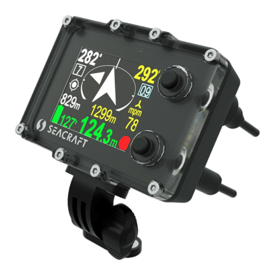
Page 8: Mechanical Construction
Mechanical construction Description of elements. 1. Universal mounting – top side 2. Ambient light sensor (do not cover) 3. Additional LED diode (red color) 4. Screen / display 5. Top button (NEXT) 6. Optional GPS buoy socket 7. Bottom button (SET, REC, HOLD) 8. -
Page 9: Basic Operation - Switching On And Off
Basic operation - switching on and off: To turn on the device - press both buttons at the same time. The device will turn on automatically after immersion in water about ≥0.5 meters deep (if the AUTO-ON function is active). If you press any button and the red led above the screen will lit and then starts blinking –... -
Page 10: Working Modes
Working modes Normal operation mode – Default mode after power on. The user sees the current dive parameters, may switch recording ON (REC) and OFF (HOLD), enter settings and view the contents of the device’s internal memory. Charging mode - When connected to a power source, a screen with the words "Charging ..." appears and most of the device's functions are blocked. - Page 11 9. REC / HOLD indicator. 10. Current compass bearing (includes all programmed corrections, including deviation and declination). 11. Number of the current marker (marker saved with the route in memory). Markers are described in the next chapter. 12. Auxiliary direction marker, a preciser (description below). 13.
-
Page 12: Additional Information Screen (Next To Main)
White – Normal operation with programmed destination Green – Destination is set and distance to it is less than 10 meters Orange – The diver is returning to the start point (distance >10 meters) Busole - Normal operation without programmed destination GPS indicator: Icon Meaning... -
Page 13: Dive Plan - Scheduled Route
1 - Course to the currently selected mission point. 2 - Estimated time to reach the selected point (when it can be calculated). 3 - Distance to the selected mission point. 4 - Current memory number / total memory available. 5 - Number of current selected mission point / number of points of mission stages. - Page 14 Intermediate points can be given in the form of GPS coordinates, MGRS coordinates, or in the form of distance-azimuth (always calculated from the previous point). Planning a route and sending the plan to the device is always done using a computer program. The ENC device can only display the details of the currently held plan and choose which stage is currently active.
- Page 15 Selected point no. 5 from the schedule with 13 It is possible to move to the next 5 points, press points - press the upper key -> the lower button -> Selected point no. 10. In the bottom line you can now see its MGRS coordinates.
- Page 16 The ability to use more Dive Plan points and text descriptions for these points will only be fully utilized when Seacraft application released in 2022 (1.1.13) or later, running on your computer. Switching between the selected points of the Dive Plan still takes place only at the explicit request of the user.
-
Page 17: Basic Information About Dive Planning Using Enc3Pro
(maybe even temporarily far from optimal). Thanks to internal calculations, the ENC3Pro device will indicate the correct, real azimuth and distance to the planned stage at any time. Using the average speed of the last 30 seconds, he will also try to estimate the time to reach the planned stage, but assuming that you can move directly in its direction, in a straight line. -
Page 18: Two Independent Modes For Navigating - Comparison
Two independent modes for navigating - comparison To extend the capabilities and range of applications of the ENC3Pro console, the ability to select how the device navigates to your destination has been introduced. This increases the usability of the device at the cost of slightly complicating its operation. Below are the characteristics of each navigation mode and the main differences between them. -
Page 19: How Do I Find Out Which Navigation Mode Is Currently Active On My Device
How do I find out which navigation mode is currently active on my device? The main screen of the ENC3Pro Navigation Console has the same layout and content for each of the available navigation modes. This layout has not changed and can be read using the information available in the previous manual. -
Page 20: How To Switch Between Navigation Modes
Already on the first screen, the second position from the top allows you to change the navigation mode. Just highlight it and press the lower button on the ENC3Pro console, and the selected mode will change as shown in the pictures below:... -
Page 21: Azimuth-Distance Mode (Marked Az./Dist.)
Azimuth-distance mode (marked Az./Dist.) After selecting this mode: - the ENC3Pro console will calculate the current position using only the compass and log (if log is used) - we can define the target point by specifying distance to it and azimuth (compass direction); the distance can be given in the range of 10m ... - Page 22 GPS position appears. The device always remembers the last good (i.e. accurate) GPS reading. If, from the moment of switching on, the ENC3Pro console does not have a single current GPS reading, then all calculations on the above-mentioned screen will be made with the use of this archived GPS point (it may even come from many days ago and indicate a distant location).
- Page 23 Next pressing NEXT changes this inscription to CLEAR TARGET - selecting this option will delete all settings - ie azimuth and distance. The ENC3Pro Console, once its target settings are cleared, will no longer display the course to the target on the main screen in the upper left corner. It will also not show the distance or time to the target in the center line.
-
Page 24: Display Content Optimization
Display content optimization Displaying all necessary information on small screen is not an easy job. Using small font is not good idea, because user may have troubles with reading it. That’s why this device has to change the displayed content with time, or use different content depending on context – for example : depending on what the user set or switch on. - Page 25 Main navigation screen if distance to the target is Main navigation screen during normal work <20 m When the currently selected point is 10 meters or less - a text description (hint) associated with that point appears just below the compass arrow. This description is shown in blue for 3 seconds, alternating with the distance values (in yellow) that would normally be there.
- Page 26 Main screen when no target is set. Main window when target is defined. Notice : red part of the busole-like arrow points North. If the MENU function is selected, the screen looks as shown: 1. Internal date (DD.MM.YY) 2. Internal time (hh:mm), in 24-hour system 3.
-
Page 27: Menu Screen- Functions Choice
MENU screen- functions choice After activating the MENU function on the additional information screen (see page 21), the user can choose one of 4 commands: Allows you to turn off the device. On the left side of the screen, the following are displayed: battery charge status (green), unique device serial number (SN) and firmware version (SV): Power off is possible. -
Page 28: Setup
SETUP This function takes you to the advanced settings of the device (details in the further part of this document). On the left a shortcut of the most important operating parameters that are currently set is displayed. Depth profile record After activating the GRAPH function from the device MENU, a screen will be displayed containing the so-called depth profile (shown below). -
Page 29: Route Recording In Xy Plot
• Data writing may be repeatedly suspended (HOLD). Due to the limited capabilities of the device, this graph does not show these gaps in any way. • You can tilt the device left or right (at least 45 degrees) to change the function of the lower button. -
Page 30: Timer / Stopwatch - Auxiliary Time Counter
Due to the limited number of buttons available in the device, additional functions when viewing the graphs are available after tilting the device at least 45 degrees to the right or left, as shown in the table below. Device in normal Device tilted right Device tilted left position... -
Page 31: Device Configuration (Setup)
Device configuration (SETUP) If you press the lower button (ENTER) when the SETUP item on the MENU screen is highlighted, you will be redirected to the SETUP menu. Device settings are organized in 2 screens. The selected function is highlighted. The top button (NEXT) will switch the selected function to the next one (below). -
Page 32: Pressure/Salinity - Pressure And Depth Correction
Pressure/salinity – pressure and depth correction This option is used to control the work of the pressure sensor and to set the salinity necessary for correct (accurate) depth determination. The first line, green, displays the external pressure currently measured by the built-in sensor, expressed in millibars. - Page 33 Field named 'Calc. Distance from ' can switch between two values: - 'External log' - distance and speed will be calculated based on signals from an external sensor (log). When selected, will be placed next to the speed display on the main navigation screen - 'Const.
- Page 34 In order to calibrate the external log, first set the known and precisely determined test distance. This distance can be 10m ... 2000m. It can be changed by pressing the lower button when the 'Reference distance' text is highlighted on the above screen. For accurate calibration, select a distance of at least 100m.
-
Page 35: Log/Speed Calibration - Detailed Information Regarding External Log Calibration
(e.g. 'nozzle effect'). The factory calibration of the log is appropriate for its use on SEACRAFT scooters, mounted in the manner indicated below. In individual cases, significantly different from the one presented above, it is recommended to recalibrate the log with all accompanying equipment that will be used in real conditions. - Page 36 = previous calibration factor (pulses / 100m) c = known actual route length Example: The recorded route has a known actual length of 127m. The ENC3Pro console registered it as 124m, working at a default ratio of 1590 pulses / 100m. After substituting for the formula: f = 124 * 1590 / 127 =1555 Then activate the log calibration procedure as described above.
-
Page 37: Gps - Checking Gps Receiver
All the ‘Calibration’ process use meters as the distance unit (knots will be too much, and feet – to little to achieve good results without additional complications of the whole procedure). Choosing the reference distance for the calibration you may use this quick reference: 100m = 109.36133 yd = 328.084 ft = 0.054 N.MI (nautical mile) 361 ft = 110.0328m (~110m with <0,03% of error) -
Page 38: Time/Date - Internal Realtime Clock
GPS screen in MGRS format First 30 seconds from the power on – you can reset the GPS receiver with the lower button. GPS information is refreshed automatically after each successful update on this screen. Green circle at the bottom will blink in each second if the connected GPS receiver is working properly. -
Page 39: Other Settings - Other Parameters
The value of 1.6m is consistent with the depth recommended in the European standard EN 13319. Auto-ON [yes / no] - If set to (yes), the ENC3Pro console will turn on automatically when immersed in water 0.3 m or more deep. This option does not allow turning off the device that... -
Page 40: Auto-Rec Option
When Auto-REC is off, the ENC will remain in HOLD state until the lower button is pressed on the main screen. User must manually start data recording to start saving data. When Auto-REC is enabled, the ENC3Pro console will automatically detect when data recording should begin. -
Page 41: Auto+Marker Option
When Auto-HOLD is turned on, the ENC console will automatically stop writing data. Automatic interruption of data recording will occur if AT LEAST ONE of the following conditions is met: - the depth measured by the ENC console has decreased to 0.2 meters or less - speed measured by speed sensor has dropped below 6 m / min and remains so for at least 1.2 seconds (without momentary speed increases) The Auto-HOLD function is responsible only for stopping the recording and works regardless of the... -
Page 42: Buttonsens
If Auto+marker is turned off, markpoints will only be saved when you stop recording manually. When the Auto+marker option is turned on, stopping the recording due to the Auto-HOLD option will cause saving and increasing the marker number in the same way, as if user will do it by his own hand. -
Page 43: Units - Display Units
Units – display units Allows you to choose the units of the values presented on the screen: Temperat.(ure) – Can be °C (Celsius) or °F (Fahrenheit) Depth – Can be meters or feet Speed – Can be m/min (meters per minute) or knots (nautical miles per hour) Distance –... - Page 44 especially when there are big distances traveled (traveling to another continent, or to a distant country). The information on the right is the time that has elapsed since the last calibration (in minutes, hours, days or '> 1y' if the time is greater than 1 year). The exact content of the compass calibration menu is shown in the next section of the manual.
-
Page 45: Compass Calibration
When the Previous field is highlighted, we can see the calibration settings that the console had previously. The device stores one previous compass calibration in its memory. Pressing the lower button when the Previous field is highlighted will cause the current compass calibration to take the values saved previously (e.g. - Page 46 The digital "calibration progress percentage" indicator is shown at the bottom left of the screen. The progress bar and digital indicator on the screen reflect the actual operation progress. If the user does not rotate the device as it should, or rotates it only in one axis all the time, the progress bar and digital indicator will remain unchanged and may even roll back after 5 minutes of inactivity.
- Page 47 You should use this option only when experienced with this device. We recommend to leave this option disabled in case of any troubles with compass operation. After each new calibration, this settings will need to be checked and/or corrected (if enabled). Proper usage of this option may require additional tools to determine required directions.
-
Page 48: Compass Sensor Checking (Diagnosis)
Caution! During the entire procedure, avoid placing near the calibrated device other elements that interfere with the magnetic field - large metal parts, cells, and even another magnetic compass. Failure to comply with this recommendation may significantly affect the effects of this procedure. It should be highlighted that mounting the device on a scooter and near other equipment (e.g. -
Page 49: Compass Install Angle Setting
Compass Install Angle setting The electronic compass built into the ENC3Pro console will work properly only if the console is mechanically connected to the body of the underwater vehicle (scooter) in a permanent manner (unchanged throughout the entire dive). In addition, it is required that the angle formed by the screen of the device with the axis of the scooter is known and constant. -
Page 50: What Is An Installation Angle And Why Is It Important
What is an installation angle and why is it important Ideally, the ENC3Pro console could be installed exactly perpendicular to the scooter hull. Such a case means that Install angle = 0 (Fig. below) However, such a case is extremely rarely possible in practice. - Page 51 Vehicle is tilted to the right side – now readings will be improper without Install Angle correction ! Vehicle not tilted – readings are still correct, regardless of the Install Angle settings To compensate tilt influence, the ENC has to know the angle between the vehicle hull and ENC itself.
- Page 52 moves, the measurement will be rejected. The measurement can be started from the beginning with the lower button. Tilt the ENC console to the position that is most comfortable for the user. Then press the lower key again. The installation angle measurement procedure allows you to set any angle that is convenient from the user's point of view.
-
Page 53: Compass Declination And Deviation
Compass declination and deviation On the Compass settings screen Declination - Allows you to set the magnetic declination appropriate to your location. The declination is related to the displacement of the magnetic pole relative to the geographical pole and its value changes both in time and depending on the location. The declination value will be added to the compass readings on the screen and will be included in the position calculation. -
Page 54: Exit - Exiting The Settings
TIPS FOR INSTALLING THE ENC3Pro CONSOLE TO THE UNDERWATER VEHICLES In order to guarantee proper operation, the ENC3Pro console must be stably mounted on a scooter or other underwater vehicle in accordance with the provided instructions for a given type of device. -
Page 55: Installation For Other Underwater Vehicles
Compass settings / Install Angle parameter is very important. Installation for other underwater vehicles. If the ENC3Pro console is to be used on other underwater equipment, please contact the manufacturer to determine how and where it should be installed, and the installation procedure. - Page 56 This method may require former additional training. Auxiliary glossary of phrases and terms used in the descriptions and menus of the ENC3Pro console. Due to the limited possibilities of presenting information on the small screen of this device, many entries have been shortened and/or simplified, and the only interface language currently available is English.
-
Page 57: Troubleshooting
Return Go back to start point Navigate Program and go to your goal Clear (Clear target) Clear (cancel target setting - delete values) Home Starting point (origin) M (ai-M) End point, final target Part (e.g. 1 of 3 parts of the coordinates in the Part MGRS record) Item... - Page 58 device should be sent to the manufacturer's service. Wash the device under a gentle stream of warm, fresh water. The device does not turn on Repeat until the symptoms automatically after immersion The pressure transducer disappear. You may leave the in water.
- Page 59 It is recommended to completely review the device's functions after 36 months from the date of purchase and then every 24 months thereafter. Notice It is a good idea to check the manufacturer’s website www.seacraft.eu and its F.A.Q. page, for information about well-known troubles and ways to manage with them.
-
Page 60: Auxiliary Windows® Software- Installation
For ease of reference, the helper software described here will be referred to as the "Seacraft application," "application," or "software" hereinafter. Auxiliary software usage After starting the Seacraft application, the main program window looks like the figure below: The application control menu can be briefly presented as an operation tree (below):... - Page 61 Main Graphs window Route list Stored Routes Export data Import Routes From File From Bluetooth Device From USB Device Mission Plan Dive Plan Planned Route Edit, Position on map, Export / Import Configuration The Configuration section allows to customize the application to the user needs and also contains some additional functions (database backup) which are seldom used.
- Page 62 Configuration Units Upgrade via Bluetooth Upgrade via USB Manual Clear data Advanced Additional settings Troubleshoot Bluetooth Upload track data via Bluetooth Upload track data via USB Backup data Restore data Send Today’s Log...
- Page 63 More detailed information about some of the commands listed above you can find in the table below : Command View and edit records downloaded from the ENC3Pro console Stored Routes to your computer Downloading route records from the ENC3Pro console to your...
- Page 64 Importing from a file is limited to the file whose data is to be processed (e.g. sent to us by another operator or copied from our own archive). Importing data from the device requires an ENC3Pro console connected to the computer with the ��...
- Page 65 Caution! The ENC3Pro console can store 50 entries in memory. Position and depth data are recorded independently of the GPS data, although they have the same marker (record number). For example, if a record of 10 routes has been stored in memory, the application may indicate to us that it processes 10, 11, 12 or even 20 files.
- Page 66 4. The route number it had in the device's memory. 5. Total number of records (separate registered data sets) accumulated for a given route 6. Route start time, according to the clock of the ENC3Pro console 7. Total distance traveled 8.
- Page 67 The application does not distinguish data in terms of which console they come from. The data is identified based on the route number and its start time. Keep this in mind if you connect different ENC consoles to the same computer. Downloading routes from the ENC console's memory to the application does not cause the ENC console's memory to be emptied.
- Page 68 Rename – you can give your own name for the route. This name will be used in this application and for the exported files. Setting the Start Point - The ENC3Pro console stores the data of the traveled route as a set of relative coordinates, which may or may not be associated with GPS records. To correctly display such a record on the map, you must indicate the actual location of its first point.
- Page 69 Please note that in order for the recorded route to be correctly plotted on the map, the ENC3Pro console compass must have the magnetic declination set correctly for the location before diving.
- Page 70 WPS means the starting point (S) and always has the coordinates 0.0 (DISTANCE, AZIMUTH). WP1 means the point visible with the number 1 in the ENC3Pro console (and so on). The ENC console always shows the last stage of a scheduled mission as M, regardless of what the application calls it.
-
Page 71: Firmware Updating
This is a good example to make the user aware that when planning a mission, only points marked as stages are really important. The role of the ENC3Pro console is to indicate their direction and distance (relative to the current actual position of the diver), and the device operator can choose the route in accordance with the possibilities offered by the real shape of the underwater terrain. - Page 72 TROUBLESHOOTING FOR FIRMWARE UPDATES If the operation fails, follow the instructions below: Symptom Solution Press STOP on the ENC3Pro console to safely stop the data The update process in the transfer operation. application has stopped for Disconnect the console from the computer and turn it off.
-
Page 73: Normal Maintenance
10 seconds, check whether the procedure helped, or ⎯ leave the ENC3Pro console turned on until the internal battery is completely discharged; To be sure, wait 1 more hour, charge the device for a minimum of 30 minutes, check whether the procedure helped. - Page 74 working properly • Fit the device on your underwater vehicle; make sure it won’t drop off or move in unpredictable way, and the wires won’t cause any troubles • Check and correct the date and time • Verify the Install Angle setting – see the chapter Compass Install Angle setting •...
-
Page 75: Enc3Pro Parts And Accessories List
ENC3Pro parts and accessories list Name Serviceable by Comments user Screen cover screw (M3x12) Not recommended 8 pcs / 1 ENC3Pro Screen cover washer (M3) Not recommended 8 pcs / 1 ENC3Pro Holder / bracket screw (M4x8) 2 pcs for each holder/bracket... -
Page 76: Before Every Dive
Tighten the union nuts without using tools. If there is residue on the threads of the joints, remove them by rubbing the thread with a cloth moistened with clean water (blue arrows). MARINE TECH SA 38-400 Krosno, ul. Zwirki i Wigury 17, POLAND service@seacraft.eu https://seacraft.eu/products/accessories-and-spares/enc3-pro/...
Need help?
Do you have a question about the ENC3Pro and is the answer not in the manual?
Questions and answers