
Related Manuals for Aeroflex 3036


Summarization of Contents
Preface
About this manual
Explains the manual's purpose, setup, configuration, and standalone/integrated use.
Intended audience
Describes engineers who need to configure and operate wideband RF digitizers.
Driver version
Discusses using supplied or latest drivers for optimum performance.
Software compatibility
Details how to check module compatibility with software versions.
Associated documentation
Lists related documentation for setup, installation, and usage.
PXI concept
Explains PXI and PXI Express standards for instrumentation.
Hybrid slot compatibility
Discusses compatibility of PXI modules with hybrid slots.
General Information
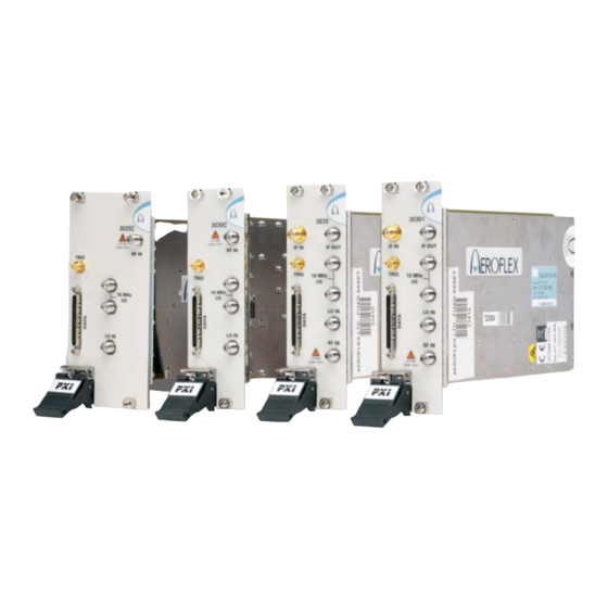
Introduction
Introduces the 3030 Series Wideband RF Digitizers and their frequency ranges.
Applications
Describes how 3030 Series modules are used in RF test and measurement systems.
Input range and accuracy
Discusses electronic switched attenuation for dynamic range and accuracy.
Data capture and processing
Explains real-time data output, internal memory capture, and digital down-conversion.
Signal routing
Details the configurable routing matrix for signal interconnection.
Triggering and synchronization
Covers synchronization to external signals and various trigger sources.
List mode overview
Explains list mode for fast settling times and instrument configuration.
Software
Lists software supplied with the module for standalone and synthesizer use.
Cleaning
Provides instructions for cleaning the module.
Calibration and servicing
Mentions calibration interval and user-serviceable parts.
Installation
Handling precautions
Refers to installation guide for handling precautions.
Hardware installation
Warns to check chassis for foreign bodies and bent pins before installation.
Connector care and maintenance
Details how to connect and torque SMA connectors.
Operation
Front-panel connectors
Identifies and describes the front-panel connectors of the 3030A/3035.
Soft front panel
Describes the soft front panel's purpose and functions.
Menu bar functions
Details the 'File' and 'Settings' options on the menu bar.
Settings\LVDS
Explains LVDS settings for clock rate, data/auxiliary/marker modes, and IF data position.
Settings\Routing Matrix
Displays the routing matrix for signal interconnection.
Settings\Optimization
Describes compensation for temperature and RF frequency response.
Instrument Options
Explains how to enable/disable instrument options with a password.
Viewing Results
Details different formats for viewing results (FFT, Time Series, IQ Polar).
FFT Display Settings
Covers graticule visibility, span selection, and saving FFT traces.
Time Series Display
Explains options for viewing Time Series data (graphs, autoscale).
Capture Modes
Details capturing data to screen or files (ASCII/binary).
RF Tuning
RF Channel Selection
Sets the currently active channel for operation.
RF Frequency and LO Position
Defines the RF input frequency and selects correction values.
External Reference Clock
Explains locking the ADC clock to 10 MHz reference or free run.
Input Conditioning
RF Input Level
Sets the peak RF input signal level for dynamic range.
IF Input Level
Sets the peak IF input signal level for dynamic range.
RF and IF Attenuation
Sets the RF and IF attenuator values to adjust input levels.
Attenuation Configuration
Explains Auto, Auto IF, and Manual attenuation configurations.
DC Offset Control
Controls DC offset and dither functions for data processing.
Acquisition and Triggering
Capture Trigger Sources
Allows selection of the trigger source from a drop-down list.
Software and Hardware Triggers
Explains software trigger mode and dependency on hardware trigger events.
Trigger Timing Parameters
Details trigger offset delay, pre-trig, and post-trig samples.
Internal Timer Trigger
Takes trigger from the internal timer and its synchronization.
Internal Level Trigger
Takes trigger from the internal level trigger.
Trigger Mode Selection
Selects internal trigger mode: Absolute or Relative.
IF/IQ Data Format
Sample Data Type
Selects IQ or IF sample data type.
Modulation Mode Settings
Sets digital modulation mode (Generic, UMTS, GSM, etc.).
Decimation Ratio
Selects decimation ratio based on modulation mode.
IQ Data Output Format
Selects 16- or 32-bit IQ data output format.
List Mode Operation
Channel List Setup
Displays individual channel list settings for list mode.
Channel Parameters
Lists editable channel parameters like Freq, LO Position, Atten Config.
List Mode Settings
Sets up addressing, strobing, and the internal counter.
Address Source Definition
Defines the source for the seven-bit-wide list address.
Program Files
Installation Location
Specifies typical installation folders for program files.
Driver Export Functions
Help File Locations
Locates help and functional documentation in the driver folder.
Online Help Contents
Shows an example of the online help contents page.
Data Connector and Timing
DATA Connector Overview
Describes the 68-way female VHDCI-type LVDS DATA connector.
DATA Pin-out Table
Provides a detailed pin-out table for the DATA connector.
Data Format Details
Explains IQ and IF data output format and IQSELECT_OUT functionality.
Data Timing Examples
Illustrates timing relationships for data transmission modes.
Brief Technical Description
Module Introduction
Describes the 3030 Series module's capabilities and architecture.
Module Block Schematics
Provides block schematics illustrating module functionality.
Need help?
Do you have a question about the 3036 and is the answer not in the manual?
Questions and answers