
Related Manuals for Mecmesin MultiTest 50-i


Summarization of Contents
Scope
Product Scope
Defines the range of force and torque testing products covered by this reference manual.
Items Supplied with the Test Stand
MultiTest-i Test Stand Components
Lists the specific components included with the MultiTest-i test stand.
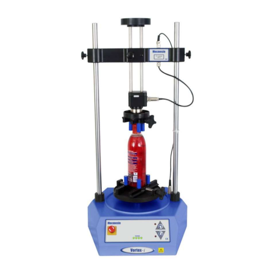
Vortex-i Test Stand Components
Lists the specific components included with the Vortex-i test stand.
Installation
Unpacking the Test Stand
Instructions for safely unpacking the test stand and checking for damage.
Lifting the Test Stand
Guidance on safe lifting procedures and using appropriate equipment.
Locating the Test Stand
Recommendations for positioning the test stand on a suitable work surface.
Mains Power Supply Connection
Details on connecting the test stand to the mains power supply and voltage selection.
MultiTest-i Assembly and Installation
Bolting the Test Stand to the Work Surface
Procedures for securing single-column stands to a bench using anchor brackets or locating eyes.
Fitting the Feet to the Stand
Instructions for attaching the rubber feet to the base of the MultiTest 2.5-i and 5-i stands.
Fitting the Loadcell to the Crosshead
Detailed steps for attaching the loadcell (ILC) to the crosshead of single-column stands.
Swapping Loadcells
Procedure for safely disconnecting and connecting different loadcells to the system.
Attaching Grips and Fixtures
Guidance on connecting grips and holding fixtures to the anvil plate and loadcell.
Setting the Limit Stops
Instructions for adjusting mechanical and software limit stops for crosshead movement.
Limits after Connection to PC with Software
How to manage crosshead limit warnings and errors when connected to the PC software.
Vortex-i Assembly and Installation
Fitting the Crosshead to the Vortex-i
Steps for mounting the crosshead onto the support columns of the Vortex-i.
Connecting the Intelligent Torque Cell
Procedure for connecting the Intelligent Torque Cell (ITC) to the Vortex-i test stand.
Swapping Intelligent Torque Cells
Process for disconnecting and replacing the Intelligent Torque Cell.
Connecting the PC (MultiTest-i and Vortex-i)
Connecting the Power Lead and USB Lead
Instructions for connecting the test stand to the PC via USB and mains power.
Emergency Stop Button Functionality
Explanation of the emergency stop button's function and how to reset it.
Jog Buttons Operation
Details on using physical and software jog buttons for crosshead/platen movement.
Installing Emperor Software on Your PC
Minimum System Requirements for Emperor
Specifies the hardware and software requirements for installing the Emperor software.
Accessing Emperor Data Folders
Information on required folder access for the Emperor software installation.
Starting and Logging into Emperor
Guide to launching the Emperor software and logging in with user credentials.
Need help?
Do you have a question about the MultiTest 50-i and is the answer not in the manual?
Questions and answers