
Related Manuals for Mecmesin MultiTest 10-i


Summarization of Contents
Items Supplied with the Test Stand
MultiTest-i Test Stand Components
Lists all components provided with the MultiTest-i test stand.
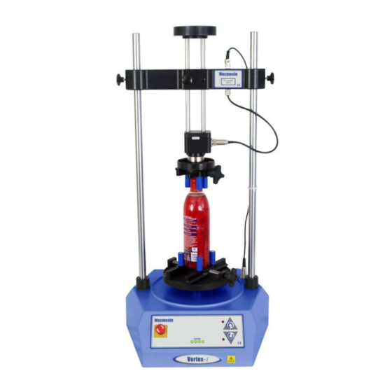
Vortex-i Test Stand Components
Lists all components provided with the Vortex-i test stand.
Installation
Unpacking the Test Stand
Instructions for unpacking and checking the test stand for damage.
Lifting and Positioning the Test Stand
Guidelines for safe lifting and placement of the test stand on a stable surface.
Mains Power Supply Connection
Information on connecting the test stand to the mains power supply.
MultiTest-i Assembly and Installation
Securing to Work Surface
Instructions for bolting single-column stands to a bench for stability.
Fitting Base Feet
Instructions for attaching rubber feet to the base of specific MultiTest models.
Fitting Loadcell to Crosshead
Steps for attaching the loadcell to the crosshead of single-column stands.
Swapping Loadcells
Procedure for disconnecting and connecting different loadcells to the system.
Attaching Grips and Fixtures
Guidance on fitting various grips and holding fixtures to the loadcell and anvil.
Setting Limit Stops
How to adjust mechanical limit stops to prevent crosshead damage.
Limits After PC Connection
System response and warnings when limits are reached during software operation.
Vortex-i Assembly and Installation
Fitting Crosshead to Vortex-i
Steps for mounting the crosshead onto the Vortex-i support columns.
Connecting Intelligent Torque Cell
How to connect the Intelligent Torque Cell (ITC) to the test stand.
Swapping Intelligent Torque Cells
Procedure for replacing the Intelligent Torque Cell (ITC) in the system.
Connecting the PC
Connecting Power and USB Leads
Instructions for connecting the test stand to the PC via USB and mains power.
Emergency Stop Button Operation
Functionality, activation, and resetting of the emergency stop button.
Jog Buttons Usage
Usage of physical and on-screen jog buttons for positioning the crosshead or platen.
Installing Emperor Software
Minimum System Requirements
Specifies hardware and OS requirements for installing Emperor software.
Access to Data Folders
Details necessary folder access permissions for correct Emperor software installation.
Starting Emperor Software
Guide to launching the Emperor software and logging in with user credentials.
Need help?
Do you have a question about the MultiTest 10-i and is the answer not in the manual?
Questions and answers