Table of Contents
Advertisement
.
.
.
p r i n t e d i n u
s
a
P-2012
Shown with optional
lock & solid door
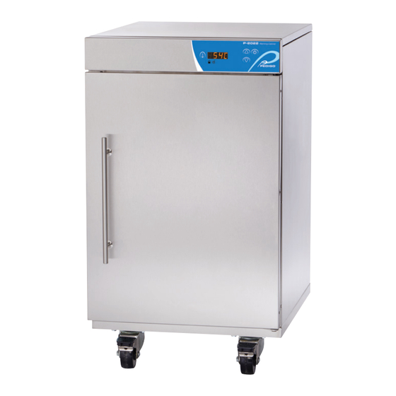
P-2022
Shown with optional solid
door, casters and plate
BLANKET WARMING CABINET
OPERATION & CARE
OPERATION & CARE
MANUAL
P-2012
P-2022
P-2032
P-2032
Shown with optional
lock and left hinged door
M N - 3 6 9 5 6 / M M - 1 0 7 4 R e v 0 ( 0 1 / 1 5 )
Advertisement
Table of Contents

Related Manuals for Pedigo P-2032


Summary of Contents for Pedigo P-2032
- Page 1 OPERATION & CARE MANUAL P-2012 P-2022 P-2032 P-2012 P-2022 P-2032 Shown with optional Shown with optional solid Shown with optional lock & solid door door, casters and plate lock and left hinged door BLANKET WARMING CABINET OPERATION & CARE p r i n t e d i n u...
-
Page 2: Table Of Contents
P-2012 . . . . . . . . . . . . . . . . . . . . -
Page 3: Environmental Conditions
D A M A G E & C L A I M S All Pedigo Products, Inc . equipment is 4 . Make certain the driver signs this receipt . If he refuses sold F .O .B . shipping point, and when to sign, make a notation of this refusal on the receipt . -
Page 4: Unpacking
U N P A C K I N G A N D S E T - U P 1 . Carefully remove the appliance from the carton (A) or crate (B) . NOTE: Do not discard the carton and other packaging material until you have inspected the unit for hidden damage and tested it for proper operation. -
Page 5: Safety Procedures And Precautions
S A F E T Y P R O C E D U R E S A N D P R E C A U T I O N S Knowledge of proper procedures is essential to the 1 . This blanket warmer is intended for warming DRY, cotton safe operation of electrically energized equipment . -
Page 6: Preparation
With casters (optional): Hazardous Voltage Present 2 .5 ft Capacity Dimensions (HxWxD) P-2012 27 .9" x 18 .5" x 26 .3" (709mm x 470mm x 669mm) With feet (standard): 67 lbs (30 kg) 135 lbs (62 kg) Weight** (est.) SHIP CRATED With casters &... -
Page 7: General Information
1" (25mm) from top and sides • Four (4) non-skid rubber feet 3/4" (19mm) from bottom are standard . P-2012 Dimensions (HxWxD) 21 .9" x 18 .5" x 26 .2" (557mm x 470mm x 666mm) With feet (standard): With casters &... - Page 8 D I M E N S I O N S P-2012 9.1 " (232mm) IEC Cord Inlet Cord length: 6 ft (1.83m) (est.) 36.0" (914mm) 26.2" (666mm) 18.5" (470mm) 22.0" (559mm) 14.5" (369mm) 18.5" (470mm) INSERT CAVITY 20.6" (523mm) 15.5" (394mm)
- Page 9 D I M E N S I O N S P-2012 (continued) 10.5 " (267mm) IEC Cord Inlet Cord length: 6 ft (1.83m) (est.) 37.4" (949mm) 26.5" (673mm) 18.5" (470mm) 22.0" (559mm) 14.5" (369mm) 18.5" (470mm) INSERT CAVITY 25.1" (631mm) 15.5"...
- Page 10 D I M E N S I O N S P-2022 9.3 " (235mm) IEC Cord Inlet Cord length: 6 ft (1.83m) (est.) 36.0" (914mm) 26.3" (669mm) 22.0" (559mm) 18.5" (470mm) 18.5" (470mm) CAVITY 14.5" (369mm) INSERT 20.6" (523mm) 15.5" (394mm) CAVITY with standard feet 9.3 "...
- Page 11 D I M E N S I O N S P-2022 (continued) 10.6 " (270mm) IEC Cord Inlet Cord length: 6 ft (1.83m) (est.) 36.3 (921mm) 26.5" (674mm) 22.0" (559mm) 18.5" (470mm) 18.5" (470mm) CAVITY 14.5" (369mm) INSERT 15.5" (394mm) 25.1"...
- Page 12 D I M E N S I O N S P-2032 12.0 " (305mm) IEC Cord Inlet Cord length: 6 ft (1.83m) (est.) 47.0" (1193mm) 28.6" (726mm) 24.0" (610mm) 24.3" (616mm) 21.0" (532mm) CAVITY 19.9" (506mm) INSERT 21.0" (533mm) 22.8" (578mm) CAVITY with standard feet 12.0 "...
- Page 13 D I M E N S I O N S P-2032 (continued) 13.4 " (340mm) IEC Cord Inlet Cord length: 6 ft (1.83m) (est.) 48.4" (1229mm) 28.8" (732mm) 24.0" (610mm) 24.3" (616mm) 21.0" (532mm) CAVITY 19.9" (506mm) INSERT 21.0" (533mm) 27.4"...
- Page 14 D I M E N S I O N S P-2032/PT 23.5" (597mm) 70.0" (1779mm) 27.2" (691mm) 12.2 " (309mm) 24.4" (619mm) IEC Cord Inlet Cord length: 6 ft (1.83m) (est.) 21.4" (543mm) CAVITY 19.9" (506mm) INSERT 23.5" (597mm) 21.0" (533mm) 27.1"...
- Page 15 D I M E N S I O N S P-2032/PT (continued) 23.5" (598mm) 70.0" (1779mm) 27.2" (691mm) 13.4 " (340mm) 24.4" (619mm) IEC Cord Inlet Cord length: 6 ft (1.83m) (est.) 21.4" (543mm) CAVITY 19.9" (506mm) INSERT 23.5" (598mm) 21.0"...
-
Page 16: General Warnings
G E N E R A L W A R N I N G S WARNING The unit requires special precautions regarding EMC A risk of increased emissions or decreased immunity (Electromagnetic Compatibility) and needs to be installed may result if the power cord attached is altered or a and put into service according to the EMC information manufacturer supplied power cable is not used . - Page 17 Guidance and manufacturer’s declaration - electromagnetic emissions The unit is intended for use in the electromagnetic environment specifi ed below. The customer or the end user of this unit should assure that it is used in such an environment . Compliance IEC 60601 test Immunity test...
-
Page 18: Blanket Control Features
B L A N K E T C O N T R O L F E A T U R E S Control and LED Display ON/OFF TEMPERATURE button button RECALL button Overtemp Button lockout DOWN indicator light indicator light button CONTROL PANEL BUTTONS L.E.D. -
Page 19: Operation Procedures
B L A N K E T C H A M B E R O P E R A T I O N P R O C E D U R E S The appliance should be plugged into an appropriate hospital grade receptacle as specifi ed on the electrical information page. -
Page 20: Protecting Stainless Steel Surfaces
C L E A N I N G A N D P R E V E N T I V E M A I N T E N A N C E PROTECTING STAINLESS STEEL, EPOXY COATED AND CLEANING AGENTS PLASTIC SURFACES Use non-abrasive cleaning products designed for use on It is important to guard against corrosion... -
Page 21: Clean The Unit Regularly
C A R E A N D C L E A N I N G The cleanliness and appearance of this equipment will contribute considerably to its operating efficiency . Make certain the cabinet and door gasket are kept free of any debris that may accumulate . -
Page 22: Troubleshooting Guide
T R O U B L E S H O O T I N G G U I D E NOTE: If your unit is not operating properly, check the following before calling your authorized service agent . Check the power applied to the unit . Verify female end of plug is securely seated in unit and that the male end of plug is in an appropriate, functioning outlet . - Page 23 *E-81 Calibration Call service not locked *E-83 EEPROM Error Call service for help resetting the control . E-87 EEPROM Error Stored offsets corrupted . Offsets reset to 0 . Control may need to be recalibrated . Possible bad EEPROM . Call service if error persists .
-
Page 24: Fuse Replacement
5017763 5017764 5017764 SEISMIC MOUNTING BRACKETS contact factory contact factory contact factory contact factory (special installation requirements apply) STACKING HARDWARE P-2012 or P-2022 over P-2012 or P-2022 5017272 5017272 — — P-2012 or P-2022 triple stacked 5017539 5017539 — —... -
Page 25: Full Assembly Service View
S E R V I C E FULL ASSEMBLY (P-2012 shown) TOP DOOR HINGE 24 24 SERIAL NUMBER IS REQUIRED FOR ALL INQUIRIES PART NUMBERS AND DRAWINGS ARE SUBJECT TO CHANGE WITHOUT NOTICE. Always include both model and serial numbers in your correspondence regarding the unit. - Page 26 SC-27406 14 . BOTTOM COVER 1014270 P-2012/P-2022 1014284 P-2032 1016407 P-2032/PT 15 . FEET FE-29203 3/4" TALL; P-2012/P-2022 BM-22606 1-1/4" TALL; P-2032 16 . PANEL, BLANKET INSERT BOTTOM 1011268 P-2012/P-2022 1011471 P-2032 PANEL, INSERT SIDE, BLANKET 17 . 1012866 P-2012...
-
Page 27: Electrical Chassis Service View
DESCRIPTION PART CABLE, RELAY BOARD CB-35193 CLIP, EDGE HOLDING CL-35031 RELAY BOARD BA-35106 P-2012 BA-35107 P-2022/ P-2032 SCREW, M3-0 .5 x 16mm, PH HD SC-22270 SPACER, 1/4" DIA x 3/8" NYLON SP-29425 POWER SUPPLY, 20W, 5 VOLTS DC OUTPUT BA-34965 SERIAL NUMBER IS REQUIRED FOR ALL INQUIRIES PART NUMBERS AND DRAWINGS ARE SUBJECT TO CHANGE WITHOUT NOTICE. -
Page 28: Cavity Sensor Service View
S E R V I C E CAVITY SENSOR ITEM DESCRIPTION PART PROBE, DUAL J-TYPE THERMISTOR PR-35492 BLOCK, SENSOR BK-29882 SCREW, M4 x 0 .7 x 10mm PAN SC-35259 SERIAL NUMBER IS REQUIRED FOR ALL INQUIRIES PART NUMBERS AND DRAWINGS ARE SUBJECT TO CHANGE WITHOUT NOTICE. Always include both model and serial numbers in your correspondence regarding the unit. -
Page 29: Control Interface Service View
S E R V I C E CONTROL INTERFACE (P-2012/P-2022 shown) ITEM DESCRIPTION PART OVERLAY P-2012 PE-37112 P-2022 PE-37111 P-2032 PE-37110 INTERFACE ASSEMBLY, 18 .5" P-2012 5018715 P - 2022 5018717 INTERFACE ASSEMBLY, 24" P-2032 5018718 SPACER, SUPPORT, NYL, 1 .4"... -
Page 30: Shelf (P-2022/P-2032) Service View
S E R V I C E SHELF (P-2022/P-2032 only) ITEM DESCRIPTION PART PANEL, TOP 1014609 INSULATION 1016823 ELEMENT, HEATER PAD P-2022 EL-37009 P-2032 EL-36992 PANEL, HEAT PAD MOUNT P-2022 1014610 P-2032 1016316 PANEL, BOTTOM P-2022 1011230 P-2032 1011597 GROMMET, NEOPRENE, BLACK BU-36408 SCREW, M4 x 0 .7 x 10mm PAN SC-22273... - Page 31 Refer to wire diagram included with the unit. M N- 3 6 95 6 / M M -1 074 Re v 0 ( 01 /1 5) • B l a nke t W a rm i n g C a bi n et O p e ra t ion & C ar e Ma n u al • 2 9...
- Page 32 This warranty 8. Promptly fi le a written claim with the carrier and attach copies of is in lieu of all other warranties expressed or implied and Pedigo all supporting paperwork. Products, Inc. neither assumes or authorizes any persons to assume...
Need help?
Do you have a question about the P-2032 and is the answer not in the manual?
Questions and answers