Table of Contents
Advertisement
Advertisement
Table of Contents

Related Manuals for Sub-Zero 700BR-2


Summarization of Contents
General Information
INTRODUCTION
Overview of the service manual's purpose and scope.
IMPORTANT SAFETY INFORMATION
Details on product safety labels and signal words (WARNING, CAUTION, NOTE).
TECHNICAL ASSISTANCE
Contact information and hours for Sub-Zero technical support.
WARRANTY INFORMATION
Summary of warranty periods and details for different unit types.
MODEL DESCRIPTIONS
Brief descriptions of the 700 Series models covered in the manual.
MODEL 700TR-2
Description and diagram of the 700TR-2 Tall Refrigerator model.
MODEL 700TF-2
Description and diagram of the 700TF-2 Tall Freezer model.
MODEL 700TFI-2
Description and diagram of the 700TFI-2 Tall Freezer model with icemaker.
MODEL 700TF-2V
Description and diagram of the 700TF-2V Tall Freezer model with variable speed compressor.
MODEL 700TFI-2V
Description and diagram of the 700TFI-2V Tall Freezer model with icemaker and variable speed compressor.
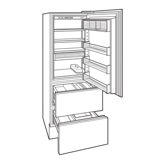
MODEL 700BR-2
Description and diagram of the 700BR-2 Base Refrigerator model.
MODEL 700BF-2
Description and diagram of the 700BF-2 Base Freezer model.
MODEL 700BFI-2
Description and diagram of the 700BFI-2 Base Freezer model with icemaker.
Installation Information
INSTALLATION CONSIDERATIONS
Common installation issues affecting service and customer complaints.
Unit Leveling
Procedure for leveling the unit using front leveling legs and adjusting screws.
Door and Drawer Adjustment
Information on adjusting door/drawer panels and the importance of leveling.
Door Stop Adjustment
How to adjust the 90° door stop cam on tall units using a screwdriver.
Dual Unit Installations
Guidelines for installing multiple units side-by-side with heater packages.
Electronic Control
SECTION 3
Section title for Electronic Control System Information.
ELECTRONIC CONTROL SYSTEM INFORMATION
Overview of the electronic control system for tall and base units.
ELECTRONIC CONTROL TERMINOLOGY & COMPONENT DESCRIPTIONS
Definitions of electronic control terms and descriptions of key components.
BASIC 700-2 TALL UNIT ELECTRONIC CONTROL SYSTEM
Illustrates the basic electronic control system for 700TC/I-2 model.
700-2 TALL UNIT CONTROL BOARD LAYOUT AND SUMMARY TABLE
Diagram and table detailing control board connection points and functions.
700-2 TALL UNIT CONTROL PANEL LAYOUT
Illustration of the control panel layout for tall units.
BASIC 700-2 TALL UNIT ELECTRONIC CONTROL INPUT OPERATIONS
Explains basic input operations for the tall unit control panel.
Adjusting Set-Point (Temperature Adjustment)
Procedure for adjusting compartment temperatures using WARMER/COLDER keys.
Icemaker System ON/OFF
How to turn the icemaker system on and off via the control panel.
Door Ajar Alarm ON/OFF
How to enable or disable the door ajar alarm feature on the control panel.
FUNCTIONS OF 700 TALL UNIT ELECTRONIC CONTROL SYSTEM
Explains monitoring, regulating, and controlling functions of the electronic control system.
Supply Power to the Lighting System
Describes how power is supplied to the lighting system via the control board.
Monitor, Regulate and Display Compartment Temperatures (700TC/I-2, 700TR-2 and 700TF/I-2)
How the microprocessor monitors and displays compartment temperatures.
Control Variable Speed Compressor (700TF/I-2V)
Explanation of how the variable speed compressor is controlled by the compressor controller.
Control Condenser Fan Run
How the microprocessor senses compressor operation to control the condenser fan.
Monitor Compressor Run Duration, Displays If Service may be Needed (700TC/I-2, 700TR-2 and 700TF/I-2)
How the microprocessor monitors compressor run time and indicates potential service needs.
Monitor and Control “Adaptive Defrost” of Freezer Evaporator
Explanation of the adaptive defrost technique for the freezer evaporator.
Monitor Speed Signal of Variable Speed Compressor Controller, Displays If Service may be Needed (700TF/I-2V)
How the microprocessor monitors speed signals to the variable speed compressor controller.
Monitor Icemaker System and Display If Service is Needed
How the microprocessor monitors the icemaker water valve solenoid and displays service needs.
UNIQUE 700-2 TALL UNIT ELECTRONIC CONTROL INPUT OPERATIONS
Covers unique input operations like temperature unit selection and Sabbath mode.
Temperature Unit Selection Mode (Selecting Degrees Fahrenheit or Degrees Celsius Display)
How to convert temperature units between Fahrenheit and Celsius on the control panel.
Sabbath Mode
Explanation of Sabbath Mode and its effect on unit functions.
Showroom Mode
How to initiate and exit Showroom Mode, disabling cooling functions.
Manual Compartment Disable Mode
Allows disabling one compartment's cooling for cleaning or service.
Manual Freezer Evaporator Defrost
Procedure to manually initiate freezer evaporator defrost for servicing.
POSSIBLE 700-2 TALL UNIT ERROR INDICATORS
Illustrates common error indicators seen on the LCD display for tall units.
POSSIBLE 700-2 BASE UNIT ERROR INDICATORS
Illustrates common error indicators seen on the LCD display for base units.
POSSIBLE 700-2 BASE UNIT ERROR INDICATORS
Continues illustration of common error indicators for base units.
700-2 TALL UNIT ELECTRONIC CONTROL TROUBLESHOOTING INPUT OPERATIONS
Explains troubleshooting operations like Diagnostic Mode.
Diagnostic Mode
Procedure to initiate Diagnostic Mode for observing real-time temperature readings.
700-2 BASE UNIT ELECTRONIC CONTROL TROUBLESHOOTING INPUT OPERATIONS
Explains troubleshooting input operations for base units, specifically Diagnostic Mode.
Diagnostic Mode
Procedure to initiate Diagnostic Mode for base units, with thermistor location codes.
Error Code Table
Table listing error codes, their indications, and troubleshooting steps.
Manual Component Activation Mode
Allows service technicians to energize components like compressors and fans for testing.
Temperature Log Recall Mode
Accessing temperature history data stored by the electronic control system.
Initiate Temperature Log Recall Mode To View Compartment and Evaporator Temperature History
Procedure to view both compartment and evaporator temperature history.
Possible Event Indicators During Temperature Log Recall Mode(s)
Explains event indicators that may appear during temperature log recall.
Temperature Log Index Chart
Chart mapping index numbers to hours past for temperature logging.
BASIC 700-2 BASE UNIT ELECTRONIC CONTROL SYSTEM
Illustrates the basic electronic control system for a 700-2 base unit.
700-2 BASE UNIT CONTROL BOARD LAYOUT AND SUMMARY TABLE
Diagram and table detailing control board connection points and functions.
700-2 BASE UNIT CONTROL PANEL LAYOUT
Illustrations of control panel layouts for 700BR-2 and 700BF/I-2 models.
BASIC 700-2 BASE UNIT ELECTRONIC CONTROL INPUT OPERATIONS
Basic input operations for the 700-2 base unit control panel.
Unit ON/OFF
How to turn the base unit ON and OFF using the control panel.
Adjusting Set-Point (Temperature Adjustments)
Procedure for adjusting compartment temperatures on base units.
Drawer Ajar Alarm ON/OFF
How to enable/disable the drawer ajar alarm feature on base units.
Icemaker System ON/OFF (700BFI-2 Only)
How to turn the icemaker system on and off for the 700BFI-2 model.
FUNCTIONS OF 700 BASE UNIT ELECTRONIC CONTROL SYSTEM
Explains monitoring, regulating, and controlling functions for base units.
Supply Power to the Lighting System
Describes power supply to the lighting system for base units.
Monitor, Regulate and Display Two Separate Compartment Temperatures in the 700BR-2
How the 700BR-2 monitors and displays temperatures using an air baffle.
Monitor, Regulate and Display Temperatures in the 700BF/I-2
How the 700BF/I-2 monitors and displays temperatures for its single compartment zone.
Monitor and Control Refrigerator Off-Cycle Defrost in the 700BR-2
Describes refrigerator off-cycle defrost sequence in the 700BR-2.
Monitor and Control “Adaptive Defrost” in the 700BF/I-2
Explanation of the adaptive defrost technique for the 700BF/I-2 freezer evaporator.
UNIQUE 700-2 BASE UNIT ELECTRONIC CONTROL INPUT OPERATIONS
Covers unique input operations for base units like temperature unit selection and Sabbath mode.
Temperature Units Selection Mode (Selecting Degrees Fahrenheit or Degrees Celsius Display)
How to convert temperature units on base units.
Sabbath Mode
Explanation of Sabbath Mode for base units.
Showroom Mode
How to initiate and exit Showroom Mode for base units.
Manual Freezer Evaporator Defrost (700BF/I-2 Only)
Procedure to manually initiate freezer evaporator defrost on 700BF/I-2 models.
POSSIBLE 700-2 BASE UNIT ERROR INDICATORS
Illustrates common error indicators for base units like 700BR-2 and 700BF/I-2.
700-2 BASE UNIT ELECTRONIC CONTROL TROUBLESHOOTING INPUT OPERATIONS
Explains troubleshooting input operations for base units, specifically Diagnostic Mode.
Diagnostic Mode
Procedure to initiate Diagnostic Mode for base units, with thermistor location codes.
ADDITIONAL 700-2 BASE UNIT ELECTRONIC CONTROL NOTES
Notes on specific base unit features like dwell time, error codes, and modes.
Sealed System Information
HFC-134a REFRIGERANT SERVICE INFORMATION
General rules and procedures for working with HFC-134a refrigerant.
General Rules for Working with 134a Refrigerant
Essential guidelines for handling 134a refrigerant and associated service practices.
SEALED SYSTEM REPAIR PROCEDURES
Detailed service procedures for various sealed system problems.
SEALED SYSTEM OPERATION
Explanation of basic sealed system components and refrigerant flow.
Compressor (Figure 4-1)
Role of the compressor in creating pressure differences within the sealed system.
Condenser (Figure 4-2)
Function of the condenser in dissipating heat from the refrigerant.
Filter-Drier (Figure 4-3)
Purpose of the filter-drier in removing moisture from the refrigerant.
Capillary Tube (& Heat Exchanger) (Figure 4-4)
Function of the capillary tube and heat exchanger in regulating refrigerant flow and temperature.
Evaporator (Figure 4-5)
Role of the evaporator in vaporizing refrigerant and absorbing compartment heat.
Suction Line (& Heat Exchanger) (Figure 4-6)
Path of cool gas through the suction line and its heat exchange function.
SEALED SYSTEM REFRIGERANT FLOW DIAGRAMS
Refrigerant flow diagrams for Model 700TC/I-2.
Model 700TR-2 Refrigerant Flow (Figure 4-8)
Refrigerant flow diagram specific to the Model 700TR-2.
Model 700TF/I-2 and 700TF/I-2V Refrigerant Flow (Figure 4-9)
Refrigerant flow diagrams for Models 700TF/I-2 and 700TF/I-2V.
Model 700BR-2 Refrigerant Flow (Figure 4-10)
Refrigerant flow diagram for Model 700BR-2.
Model 700BF/I-2 Refrigerant Flow (Figure 4-11)
Refrigerant flow diagram for Model 700BF/I-2.
Airflow & Fan Blade Spacing
700TR-2 Air Flow and Fan Blade Spacing (Figure 5-2)
Diagram illustrating airflow and fan blade spacing for the 700TR-2 model.
700TC/I-2 Air Flow and Fan Blade Spacing (Figure 5-1)
Diagram showing airflow and fan blade spacing for the 700TC/I-2 model.
700BR-2 Air Flow and Fan Blade Spacing (Figure 5-4)
Diagram illustrating airflow and fan blade spacing for the 700BR-2 model.
700BF/I-2 Air Flow and Fan Blade Spacing (Figure 5-5)
Diagram showing airflow and fan blade spacing for the 700BF/I-2 model.
Icemaker Operation
MODULAR ICEMAKER
Introduction to the modular icemaker and its operational cycle.
Modular Icemaker Operation
Explanation of the icemaker's operational cycle involving thermostat, motor, and drive gear contacts.
Additional Icemaker Operation Notes
Notes regarding icemaker activation, dwell time, ice bucket position, and shut-off arm.
What Happens During Ejector Blade Rotation (Figure 6-2)
Diagram illustrating the ejector blade rotation and its diagnostic relevance.
MODULAR ICEMAKER TEST PROCEDURES
Tests to perform if the icemaker is suspected to be defective, including voltage and continuity tests.
WATER FILL ADJUSTMENT (Figure 6-4)
How to adjust the water fill amount using the adjustment screw.
ICEMAKER DISASSEMBLY
Procedures for removing the module/motor, mold/heater, ejector blades, and thermostat.
Component Access/Removal
COMPONENT ACCESS AND REMOVAL
Explains how to access and remove components from 700-2 Series units, divided by tall and base units.
700-2 TALL UNIT EXTERIOR COSMETIC AND MECHANICAL COMPONENTS
Procedures for removing exterior cosmetic and mechanical components of tall units.
Kickplate/Grille Removal (All Tall Units)
Steps to remove the kickplate/grille from tall units.
Side Trim Molding Strip Removal (All Tall Units)
Steps to remove side trim molding strips from tall units.
Upper Door Compartment Light Switch & Fan Switch Removal (All Tall Units)
Procedure to access and remove upper door compartment light and fan switches.
Drawer Assembly Removal (All Tall Units)
Steps to remove drawer assemblies from tall units.
Door & Drawer Gasket Removal (All Tall Units)
How to remove door and drawer gaskets from tall units.
Door Assembly Removal (All Tall Units)
Detailed steps for removing the door assembly from tall units.
Upper and Lower Hinge Assembly Removal (All Tall Units)
Procedure for removing hinge assemblies from tall units.
700-2 TALL UNIT INTERIOR COSMETIC, MECHANICAL AND ELECTRICAL COMPONENTS
Accessing interior components of tall units.
Door Shelf and Dairy Compartment Adjustment / Removal (All Tall Units)
How to adjust or remove door shelves and dairy compartments in tall units.
Compartment Shelf Adjustment / Removal (All Tall Units)
Steps for adjusting or removing compartment shelves in tall units.
Upper Light Diffuser Removal (All Tall Units)
Procedure to remove the upper light diffuser from tall units.
Light Bulb Removal (All Tall Units)
How to remove and install light bulbs in tall units.
Control Board Removal (All Tall Units)
Detailed steps for accessing and removing the control board in tall units.
Control Panel Assembly Removal (All Tall Units)
Procedure to remove the control panel assembly from tall units.
Upper Evaporator Cover / Air Duct Removal (All Tall Units)
Steps to remove the upper evaporator cover or air duct in tall units.
Upper Evaporator Fan Shroud Assembly Removal (All Tall Units)
Procedure to remove the upper evaporator fan shroud assembly in tall units.
Upper Compartment Evaporator Fan Assembly Removal (All Tall Units)
Steps to remove the upper compartment evaporator fan assembly from tall units.
Upper Compartment Thermistor Removal (All Tall Units)
Procedure to remove the upper compartment thermistor in tall units.
Upper Evaporator Thermistor Removal (700TC/I-2, 700TR-2)
Steps to remove the upper evaporator thermistor for specific tall models.
Drawer Closer Assembly Removal (All Tall Units)
Procedure to remove drawer closer assemblies from tall units.
Drawer Slide Assembly Removal (All Units)
Steps to remove drawer slide assemblies from all units.
Icemaker Assembly Removal (700TCI-2, 700TFI-2, 700TFI-2V)
Procedure to remove the icemaker assembly from specific tall models.
Heat Exchanger Cover Removal (All Tall Units)
Steps to remove the heat exchanger cover from tall units.
Lower Evaporator Cover Assembly Removal (700TR-2 Only)
Procedure to remove the lower evaporator cover assembly for the 700TR-2 model.
Lower Evaporator Fan Assembly Removal (700TR-2 Only)
Steps to remove the lower evaporator fan assembly for the 700TR-2 model.
Lower Compartment Thermistor Removal (700TR-2 Only)
Procedure to remove the lower compartment thermistor for the 700TR-2 model.
Lower Evaporator Thermistor Removal (700TR-2 Only)
Steps to remove the lower evaporator thermistor for the 700TR-2 model.
Lower Evaporator Cover Assembly Removal (700TC/I-2, 700TF/I-2, 700TF/I-2V)
Procedure to remove the lower evaporator cover assembly for specific tall models.
Drain Trough Heater Removal (700TC/I-2, 700TF/I-2, 700TF/I-2V)
Steps to remove the drain trough heater from specific tall models.
Lower Evaporator Fan Shroud Removal (700TC/I-2)
Procedure to remove the lower evaporator fan shroud for the 700TC/I-2 model.
Lower Evaporator Fan Assembly Removal (700TC/I-2)
Steps to remove the lower evaporator fan assembly for the 700TC/I-2 model.
Defrost Terminator Removal (700TC/I-2, 700TF/I-2, 700TF/I-2V)
Procedure to remove the defrost terminator from specific tall models.
Defrost Heater Removal (700TC/I-2, 700TF/I-2, 700TF/I-2V)
Steps to remove the defrost heater from specific tall models.
Switch Enclosure Assembly Removal (All Tall Units)
Procedure to remove the switch enclosure assembly from tall units.
Lower Evaporator Thermistor Removal (700TC/I-2, 700TF/I-2, 700TF/I-2V)
Steps to remove the lower evaporator thermistor for specific tall models.
Lower Compartment Thermistor Removal (700TC/I-2, 700TR-2)
Procedure to remove the lower compartment thermistor for specific tall models.
Fill Tube Heater Removal (700TC/I-2, 700TF/I-2, 700TF/I-2V)
Steps to remove the fill tube heater from specific tall models.
Lower Compartment Light Switch / Fan Switch / Icemaker Switch Removal (All Tall Units)
Procedure to remove switches from the lower compartment of tall units.
700-2 TALL UNIT COMPRESSOR AREA ELECTRICAL AND MECHANICAL COMPONENTS
Accessing electrical and mechanical components in the compressor area of tall units.
Icemaker Water Valve Removal (700TCI-2, 700TFI-2, 700TFI-2V)
Steps to remove the icemaker water valve assembly from specific tall models.
Condenser Fan Assembly Removal (All Tall Units Except 700TF/I-2V)
Procedure to remove the condenser fan assembly from tall units, excluding one model.
Condenser Fan Assembly Removal (700TF/I-2V)
Steps to remove the condenser fan assembly specifically for the 700TF/I-2V model.
Compressor Controller Removal (700TF/I-2V)
Procedure to remove the compressor controller from the 700TF/I-2V model.
700-2 TALL UNIT SEALED SYSTEM COMPONENTS
Accessing sealed system components in tall units.
Upper Refrigerator Compartment Evaporator Removal (700TCI-2, 700TR-2)
Steps to remove the upper refrigerator evaporator for specific tall models.
Lower Compartment Evaporator Removal (All Tall Units)
Procedure to remove the lower compartment evaporator from all tall units.
High-Side Filter-Drier Removal (All Tall Units)
Steps to remove the high-side filter-drier from all tall units.
Compressor Removal (All Tall Units)
Procedure to remove the compressor from all tall units, including safety precautions.
Condenser Removal (All Tall Units)
Steps to remove the condenser from all tall units, including refrigerant evacuation.
Upper Compartment Heat Exchanger Removal (700TC/I-2, 700TR-2)
Procedure to remove the upper compartment heat exchanger for specific tall models.
Lower Compartment Heat Exchanger Removal (All Tall Units)
Steps to remove the lower compartment heat exchanger from all tall units.
700-2 BASE UNIT EXTERIOR COSMETIC AND MECHANICAL COMPONENTS
Procedures for removing exterior components of base units.
Kickplate/Grille Removal (All Base Units)
Steps to remove the kickplate/grille from base units.
Drawer Assembly Removal (All Base Units)
Procedure to remove drawer assemblies from base units, including control cable disconnection.
Side Trim Molding Strip Removal (All Base Units)
Steps to remove side trim molding strips from base units.
Drawer Gasket Removal (All Base Units)
How to remove drawer gaskets from base units.
700-2 BASE UNIT INTERIOR COSMETIC, MECHANICAL AND ELECTRICAL COMPONENTS
Accessing interior components of base units.
Control Panel Assembly Removal (All Base Units)
Procedure to remove the control panel assembly from base units.
Control Cable Removal (All Base Units)
Steps to remove the control cable connecting the control panel and the back duct.
Lighting Removal (All Base Units)
How to remove and replace light bulbs and sockets in base units.
Mullion Divider Assembly Removal (700BR-2 Only)
Procedure to remove the mullion divider assembly for the 700BR-2 model.
Mullion Divider Supports Removal (700BR-2 Only)
Steps to remove the mullion divider supports for the 700BR-2 model.
Drawer Closer Assembly Removal (All Base Units)
Procedure to remove drawer closer assemblies from base units.
Drawer Slide Assembly Removal (All Base Units)
Steps to remove drawer slide assemblies from base units.
Reed Switch & Compartment Thermistor Removal (All Base Units)
Procedure to remove reed switches and compartment thermistors from base units.
Icemaker Assembly and Fill Tube Heater Removal (700BFI-2 Only)
Steps to remove the icemaker assembly and fill tube heater for the 700BFI-2 model.
Sump Cover Assembly Removal (All Base Units)
Procedure to remove the sump cover assembly from base units.
Evaporator Thermistor Removal (All Base Units)
Steps to remove the evaporator thermistor from base units.
Defrost Terminator Removal (700BF/I-2 Only)
Procedure to remove the defrost terminator for the 700BF/I-2 model.
Defrost Heater Removal (700BF/I-2 Only)
Steps to remove the defrost heater for the 700BF/I-2 model.
Control Board Assembly Removal (All Base Units)
Procedure to remove the control board assembly from base units.
Back Air Duct Assembly Removal (All Base Units)
Steps to remove the back air duct assembly from base units.
Baffle Control Removal (700BR-2 Only)
Procedure to remove the baffle control from the 700BR-2 model.
Icemaker Switch Removal (700BFI-2 Only)
Steps to remove the icemaker switch from the 700BFI-2 model.
Evaporator Fan Assembly Removal (All Base Units)
Procedure to remove the evaporator fan assembly from base units.
Icemaker Water Valve Removal (700BFI-2 Only)
Steps to remove the icemaker water valve assembly from the 700BFI-2 model.
Condenser Fan Assembly Removal (All Base Units)
Procedure to remove the condenser fan assembly from base units.
Drain Tube Heater Removal (700BF/I-2 Only)
Steps to remove the drain tube heater for the 700BF/I-2 model.
700-2 BASE UNIT SEALED SYSTEM COMPONENTS
Accessing sealed system components in base units.
High-Side Filter-Drier Removal (All Base Units)
Steps to remove the high-side filter-drier from all base units.
Compressor Removal (All Base Units)
Procedure to remove the compressor from all base units, including safety precautions.
Condenser Removal (All Base Units)
Steps to remove the condenser from all base units, including refrigerant evacuation.
Evaporator / Heat Exchanger Assembly Removal (All Base Units)
Procedure to remove the evaporator/heat exchanger assembly from base units.
Troubleshooting Guides
TROUBLESHOOTING GUIDES
Introduction to the troubleshooting section, covering error codes and general guides.
HOW TO USE THE ERROR CODE TROUBLESHOOTING GUIDE
Instructions on how to interpret and use the error code troubleshooting guide.
Error Code Table
Table listing error codes, their indications, and troubleshooting steps.
ERROR CODE TROUBLESHOOTING GUIDE
Detailed troubleshooting steps for specific error codes (05-08).
ERROR CODE TROUBLESHOOTING GUIDE
Detailed troubleshooting steps for specific error codes (20-80).
ERROR CODE TROUBLESHOOTING GUIDE
Detailed troubleshooting steps for specific error codes (81-88).
HOW TO USE THE GENERAL TROUBLESHOOTING GUIDE
Guide on how to use the general troubleshooting guide for tall units.
For Tall Unit Temperature Problems - Prior to Serial #1759493
Troubleshooting steps for tall unit temperature issues before a specific serial number.
For Tall Unit Temperature Problems - Starting with Serial #1759493
Troubleshooting steps for tall unit temperature issues from a specific serial number onwards.
Thermistor Location Code Tables
Tables mapping thermistor locations to codes for different models.
For Base Unit Temperature Problems - Regardless of Serial Number
Troubleshooting steps for base unit temperature issues, applicable to all serial numbers.
GENERAL TROUBLESHOOTING GUIDE LAYOUT
Explains the layout and organization of the general troubleshooting guide.
Tall Units - A through X
Troubleshooting problems and causes for tall units, categorized by letters A-X.
A.) Warm Freezer Temperature with “SERVICE” Flashing
Troubleshooting steps for warm freezer temperatures with SERVICE flashing.
A.) Warm Freezer Temperature with “SERVICE” Flashing (Continued)
Continued troubleshooting steps for warm freezer temperatures with SERVICE flashing.
B.) Warm Freezer Temperatures without “SERVICE” Flashing
Troubleshooting steps for warm freezer temperatures without SERVICE flashing.
B.) Warm Freezer Temperatures without “SERVICE” Flashing (Continued)
Continued troubleshooting steps for warm freezer temperatures without SERVICE flashing.
C. Warm Refrigerator Temperatures with “SERVICE” Flashing
Troubleshooting steps for warm refrigerator temperatures with SERVICE flashing.
C. Warm Refrigerator Temperatures with “SERVICE” Flashing (Continued)
Continued troubleshooting steps for warm refrigerator temperatures with SERVICE flashing.
D. Warm Refrigerator Temperatures without “SERVICE” Flashing
Troubleshooting steps for warm refrigerator temperatures without SERVICE flashing.
D. Warm Refrigerator Temperatures without “SERVICE” Flashing (Continued)
Continued troubleshooting steps for warm refrigerator temperatures without SERVICE flashing.
E. Warm or Normal Temperatures in Both Compartments with “SERVICE” Flashing
Troubleshooting steps for warm/normal temps in both compartments with SERVICE flashing.
F. Warm or Normal Temp. in One or Both Compartment with “SERVICE” Flashing and “EC” on the LCD
Troubleshooting for warm/normal temps with SERVICE flashing and EC indicator.
G. Warm or Normal Temp. in One or Both Compartment with “SERVICE” Steady, but not Flashing on the LCD
Troubleshooting for warm/normal temps with steady SERVICE indicator.
H. Warm Temperatures in Both Compartments without “SERVICE” Flashing
Troubleshooting steps for warm temperatures in both compartments without SERVICE flashing.
I. Warm or Normal Freezer Temperatures with "EE" Displayed for Freezer Temp and “SERVICE” Flashing
Troubleshooting for warm/normal freezer temps with EE and SERVICE flashing.
J. Warm or Normal Refrigerator Temperatures with "EE" Displayed for Refrigerator Temp and “SERVICE” Flashing
Troubleshooting for warm/normal refrigerator temps with EE and SERVICE flashing.
K. Product Temperature 10° or More Colder than Displayed Temperature
Troubleshooting for product temperatures significantly colder than displayed.
L. 1. “Extremely” Cold Temperatures Displayed
Troubleshooting for extremely cold temperatures displayed on the LCD.
2. If outside US - “Extremely” Warm Temperatures Displayed
Troubleshooting for extremely warm temperatures displayed, particularly outside the US.
M. "ICE" and “SERVICE” Flashing on LCD
Troubleshooting for "ICE" and "SERVICE" flashing indicators on the LCD.
N. No Ice, "ICE" Displayed on LCD, but not Flashing
Troubleshooting for no ice with "ICE" displayed but not flashing.
N. No Ice, "ICE" Displayed on LCD, but not Flashing (Continued)
Continued troubleshooting for no ice with "ICE" displayed but not flashing.
O. No Ice and "ICE" Not Displayed on LCD
Troubleshooting for no ice and no "ICE" display on the LCD.
P. Icemaker produces Too much ice
Troubleshooting for icemakers producing excessive amounts of ice.
Q. Icemaker Produces Hollow Cubes
Troubleshooting for icemakers producing hollow ice cubes.
R. Icemaker Produces Small cubes
Troubleshooting for icemakers producing small ice cubes.
S. Water in Ice Bucket / Clump of Ice in Ice Bucket
Troubleshooting for water or ice clumps in the ice bucket.
T. Membrane Switch on Control Board Malfunctioning
Troubleshooting for malfunctioning membrane switches on the control board.
U. No Lights
Troubleshooting steps for situations where there are no lights on the unit.
V. Lights Stay ON when Door &/or Drawers Are Closed (May be Accompanied by Door/Drawer Ajar Alarm Bell)
Troubleshooting for lights staying on when doors/drawers are closed.
W. Door or Drawers Not Able to Close Completely
Troubleshooting for doors or drawers that cannot close completely.
X. Door or Drawers Uneven
Troubleshooting for uneven doors or drawers, including alignment and leveling.
SEALED SYSTEM TROUBLESHOOTING / DIAGNOSTICS TABLES
Tables for diagnosing sealed system issues based on pressures and temperatures.
NORMAL OPERATING PRESSURES
Table of normal low-side and high-side operating pressures for various models.
EVAPORATOR TEMPERATURE / SEALED SYSTEM LOW-SIDE PRESSURE CORRELATION
Table correlating evaporator temperatures with sealed system low-side pressures.
TALL UNIT MEMBRANE SWITCH / RIBBON CABLE TEST
Procedure for testing the membrane switch and ribbon cable integrity on tall units.
BASE UNIT MEMBRANE SWITCH / RIBBON CABLE TEST
Procedure for testing the membrane switch and ribbon cable integrity on base units.
TALL UNIT DOOR HINGE OPERATION TEST PROCEDURES AND CORRECTIONS
Procedures for testing and correcting door hinge operation issues on tall units.
Technical Data
Model 700TC/I-2
Technical specifications for the 700TC/I-2 model, including charge, pressures, and component data.
Model 700TR-2
Technical specifications for the 700TR-2 model, including charge, pressures, and component data.
Model 700TF/I-2
Technical specifications for the 700TF/I-2 model, including charge, pressures, and component data.
Model 700TF/I-2V
Technical specifications for the 700TF/I-2V model, including charge, pressures, and component data.
Model 700BR-2
Technical specifications for the 700BR-2 model, including charge, pressures, and component data.
Model 700BF/I-2
Technical specifications for the 700BF/I-2 model, including charge, pressures, and component data.
General Information
SECTION 10
Section title for Wiring Diagrams and Schematics.
WIRING DIAGRAMS AND SCHEMATICS
Introduction to wiring diagrams and schematics, with a note on using supplied diagrams.
WIRING DIAGRAM MODEL: 700TC/I-2 (Prior to Serial #1755730)
Wiring diagram for Model 700TC/I-2 prior to a specific serial number.
WIRING SCHEMATIC MODEL: 700 TC/I-2 (Prior to Serial #1755730)
Wiring schematic for Model 700 TC/I-2 prior to a specific serial number.
WIRING DIAGRAM MODEL: 700TC/I-2 (Starting With Serial #1755730)
Wiring diagram for Model 700TC/I-2 starting from a specific serial number.
WIRING SCHEMATIC MODEL: 700 TC/I-2 (Starting with Serial #1755730)
Wiring schematic for Model 700 TC/I-2 starting from a specific serial number.
WIRING DIAGRAM MODEL: 700TR-2 (Prior to Serial #1755266)
Wiring diagram for Model 700TR-2 prior to a specific serial number.
WIRING SCHEMATIC MODEL: 700TR-2 (Prior to Serial #1755266)
Wiring schematic for Model 700TR-2 prior to a specific serial number.
WIRING DIAGRAM MODEL: 700TR-2 (Starting with Serial #1755266)
Wiring diagram for Model 700TR-2 starting from a specific serial number.
WIRING SCHEMATIC MODEL: 700TR-2 (Starting with Serial #1755266)
Wiring schematic for Model 700TR-2 starting from a specific serial number.
WIRING DIAGRAM MODEL: 700 TF/I-2 (Prior to Serial #1752891)
Wiring diagram for Model 700 TF/I-2 prior to a specific serial number.
WIRING SCHEMATIC MODEL: 700 TF/I-2 (Prior to Serial #1752891)
Wiring schematic for Model 700 TF/I-2 prior to a specific serial number.
WIRING DIAGRAM MODEL: 700 TF/I-2 (From Serial #1752891 to Serial #1898164)
Wiring diagram for Model 700 TF/I-2 within a specific serial number range.
WIRING SCHEMATIC MODEL: 700 TF/I-2 (From Serial #1752891 to Serial #1898164)
Wiring schematic for Model 700 TF/I-2 within a specific serial number range.
WIRING DIAGRAM MODEL: 700 TF/I-2V (Starting with Serial #1898164)
Wiring diagram for Model 700 TF/I-2V starting from a specific serial number.
WIRING SCHEMATIC MODEL: 700 TF/I-2V (Starting with Serial #1898164)
Wiring schematic for Model 700 TF/I-2V starting from a specific serial number.
WIRING DIAGRAM MODEL 700BR-2
Wiring diagram for Model 700BR-2, showing electrical connections and components.
WIRING SCHEMATIC MODEL: 700BR-2 (Starting with Serial #1755266)
Wiring schematic for Model 700BR-2 starting from a specific serial number.
WIRING DIAGRAM MODEL 700BF/I-2
Wiring diagram for Model 700BF/I-2, detailing component connections and wiring paths.
WIRING SCHEMATIC MODEL 700BF/I-2
Wiring schematic for Model 700BF/I-2, illustrating electrical connections and component functions.
Need help?
Do you have a question about the 700BR-2 and is the answer not in the manual?
Questions and answers