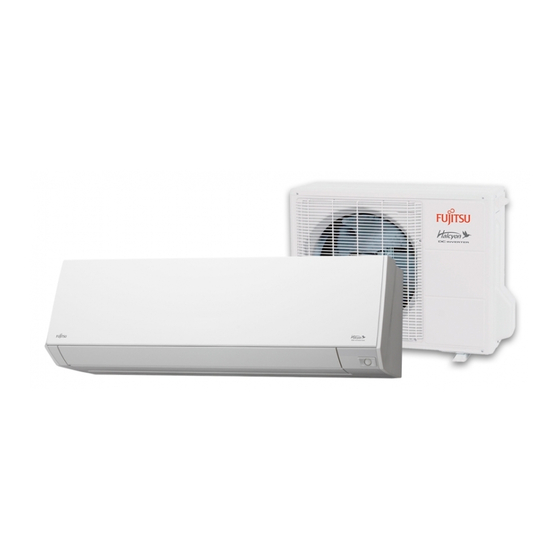
Summarization of Contents
Part 1. INDOOR UNIT
1. Specifications
Details specifications for indoor units, including performance and dimensions.
2. Wireless LAN control
Covers wireless connectivity, system requirements, and function list.
3. Dimensions
Provides physical dimensions and installation space requirements for indoor units.
4. Wiring diagrams
Illustrates electrical wiring connections for indoor units.
5. Capacity table
Lists cooling and heating capacities based on operating conditions.
6. Fan performance
Details fan speed, airflow rates, and velocity distributions.
7. Operation noise (sound pressure)
Presents noise level curves and measurement points.
8. Safety devices
Outlines safety features and protection mechanisms for indoor units.
9. External input and output
Explains external control options and status signal outputs.
10. Remote controller
Describes the wireless remote controller overview, display, and specifications.
11. Function settings
Details how to adjust various operational functions via the remote controller.
12. Accessories
Lists included accessories with the indoor unit.
13. Optional parts
Lists available optional parts for enhanced functionality.
Part 2. OUTDOOR UNIT
1. Specifications
Details specifications for outdoor units, including performance and electrical characteristics.
2. Dimensions
Provides physical dimensions and installation space requirements for outdoor units.
3. Installation space
Specifies required installation clearances for single and multiple outdoor units.
4. Refrigerant circuit
Illustrates the refrigerant flow path and key components.
5. Wiring diagrams
Illustrates electrical wiring connections for outdoor units.
6. Capacity compensation rate for pipe length and height difference
Provides rates for capacity adjustment based on pipe conditions.
7. Additional charge calculation
Details refrigerant charging for extended piping lengths and height differences.
8. Airflow
Lists airflow rates for cooling and heating modes.
9. Operation noise (sound pressure)
Presents noise level curves for outdoor unit operation.
10. Electrical characteristics
Outlines electrical properties, voltage, frequency, and wiring specifications.
11. Safety devices
Lists safety features and protection mechanisms for outdoor units.
12. Accessories
Lists included accessories with the outdoor unit.


Need help?
Do you have a question about the ASU15RLS3Y and is the answer not in the manual?
Questions and answers