Advertisement
INDOOR UNIT
SERVICE MANUAL
Models
MSZ-EF09NAW -
MSZ-EF15NAW -
MSZ-EF09NAB -
MSZ-EF15NAB -
MSZ-EF09NAS -
MSZ-EF15NAS -
MSZ-EF12NAW -
U1
MSZ-EF18NAW -
U1
MSZ-EF12NAB -
U1
MSZ-EF18NAB -
U1
MSZ-EF12NAS -
U1
MSZ-EF18NAS -
U1
Outdoor unit service manual
MXZ- ∙C∙NA(HZ) Series (OCH573)
CONTENTS
1. TECHNICAL CHANGES ······························2
2. PART NAMES AND FUNCTIONS ··················3
3. SPECIFICATION ········································4
4. OUTLINES AND DIMENSIONS ·····················6
5. WIRING DIAGRAM ·····································7
6. REFRIGERANT SYSTEM DIAGRAM ·············8
7. SERVICE FUNCTIONS ································9
8. MICROPROCESSOR CONTROL ················ 11
9. TROUBLESHOOTING ······························· 19
10. DISASSEMBLY INSTRUCTIONS ················· 31
PARTS CATALOG (OBB736)
Revision A:
• 4. OUTLINES AND DIMENTIONS has been
modified.
• Some descriptions have been modified.
OBH736 is void.
No. OBH736
REVISED EDITION-A
U1
U1
U1
U1
U1
U1
Advertisement
Table of Contents

Related Manuals for Mitsubishi MSZ-EF12NAW


Summarization of Contents
Technical Changes
Revision A Updates
Details modifications made in Revision A, including outline and dimension changes.
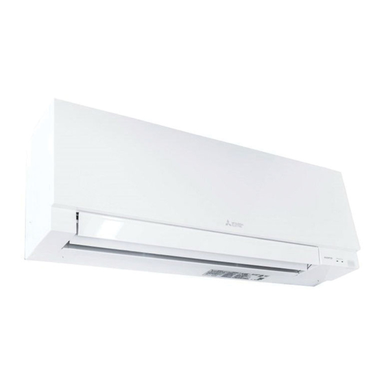
Part Names and Functions
Indoor Unit Components and Accessories
Identifies parts of the indoor unit and lists supplied accessories.
Specification
Unit Specifications
Lists technical details like power, airflow, sound level, and dimensions.
Operating Range and Conditions
Defines the temperature and humidity limits for operation.
Outlet Air Performance
Provides data on outlet air speed and coverage area for different models.
Outlines and Dimensions
Physical Dimensions and Piping
Shows the unit's physical size, mounting plate, and piping dimensions.
Wiring Diagram
Indoor Unit Wiring Schematic
Illustrates the electrical connections and components within the indoor unit.
Refrigerant System Diagram
Refrigerant Flow Path
Depicts the path of refrigerant flow in cooling and heating modes.
Service Functions
Timer and Controller Settings
Explains timer short mode and how to pair remote controllers.
Auto Restart Functionality
Details the function that automatically restarts the unit after power loss.
Microprocessor Control
Wireless Remote Controller Functions
Describes the operation and display of the wireless remote controller.
Indoor Unit Indicator Lights
Explains the meaning of the operation indicator lamp states.
Basic Operation Modes
Details Cool, Dry, Fan, and Heat operational modes and their controls.
Auto Mode and Vane Control
Covers automatic mode switching and horizontal vane operation.
Timer and Smart Set Operations
Explains weekly timer, smart set, and emergency operations.
Temperature Unit Conversion
Instructions on changing temperature display between °F and °C.
Troubleshooting
Troubleshooting Cautions and Preparations
Safety guidelines and initial checks before diagnosing issues.
Failure Recall and Error Indicators
How to retrieve fault codes and interpret operation lamp indicators.
Diagnostic Flowcharts and Component Checks
Step-by-step guides, tables, and criteria for diagnosing faults.
Wiring, Signal, and Noise Troubleshooting
Diagnosing communication errors, miswiring, and electromagnetic interference.
Test Points and Voltage References
Diagrams showing test points and expected voltage readings on PCBs.
Disassembly Instructions
Terminal Connector Handling
Guidance on detaching terminals with and without locking mechanisms.
Panel and Electrical Component Removal
Step-by-step removal of the front panel and internal electrical parts.
Nozzle, Motor, and Heat Exchanger Removal
Procedures for detaching nozzle assembly, motors, and heat exchanger.
Indoor Coil Thermistor Installation
Correct procedure for mounting the indoor coil thermistor.
Need help?
Do you have a question about the MSZ-EF12NAW and is the answer not in the manual?
Questions and answers