Advertisement
Quick Links
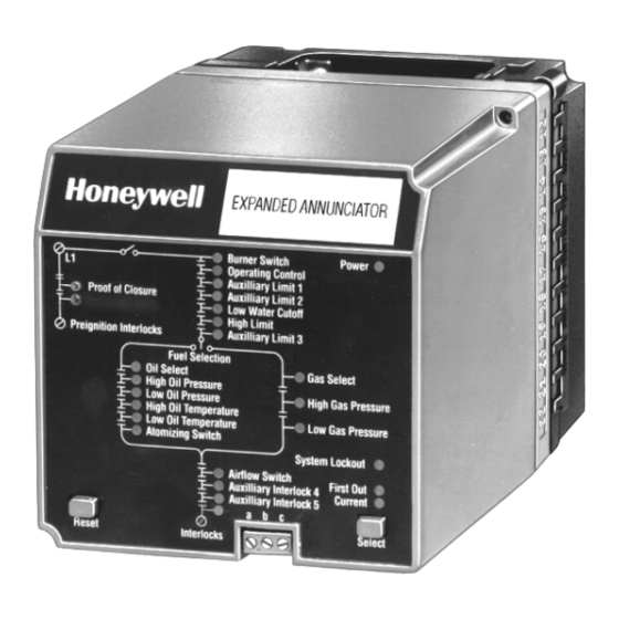
7800 SERIES
S7830
Expanded Annunciator
APPLICATION
The S7830 Expanded Annunciator is an enhancement module
for use with 7800 SERIES Relay Modules. The S7830 is a
microprocessor-based device designed to monitor the status
of a series string of limit, control, and interlock contacts for a
commercial or industrial burner. The S7830 acts as a system
monitor and enhances fault and status messages of the 7800
SERIES burner control.
FEATURES
• 26 status light emitting diodes (LED).
• Front panel LED array, arranged in a pattern to clearly
indicate the flow of line voltage through the string of
limits, controls and interlocks.
• Selectable current and first-out LED array display
status.
• Power and proper operation indicating LED.
• Common Universal Mounting Subbase (Q7800A or B).
• 21 monitored contact points.
• Access for external electrical voltage checks.
• Communication interface capability.
• Capable of programmable limit or interlock messages
using the S7800A1142 Keyboard Display Module
(KDM).
• Open Lockout interlocks are indicated with a flashing
status LED when used with Relay Module Models with
Lockout Interlock feature.
• Hold messages displayed on the KDM are enhanced
with the Expanded Annuciator terminal description
information that is causing the hold (low water cutoff
for example).
• LED operational test.
• 36 additional 7800 SERIES fault and hold messages.
Application ........................................................................
Features ...........................................................................
Specifications ...................................................................
Ordering Information .........................................................
Principal Technical Features ............................................
Installation ........................................................................
Wiring ...............................................................................
Operation .........................................................................
PRODUCT DATA
Contents
1
1
2
2
4
4
5
9
65-0101-03
Advertisement

Related Manuals for Honeywell S7830


Summarization of Contents
Features of the S7830 Expanded Annunciator
26 Status LEDs
Provides 26 status light emitting diodes for system indication.
Front Panel LED Array
Clearly indicates flow of line voltage through limits, controls, and interlocks.
Selectable LED Display Status
Offers selectable current and first-out LED array display status.
Power and Operation LED
Indicates power and proper operation status.
Universal Mounting Subbase
Utilizes common universal mounting subbase Q7800A or B.
21 Monitored Contact Points
Monitors 21 digital contact points for system status.
External Voltage Check Access
Allows access for external electrical voltage checks.
Communication Interface Capability
Features communication interface capability.
Programmable Limit/Interlock Messages
Capable of programmable limit/interlock messages via KDM.
Open Lockout Interlock Indication
Indicates open lockout interlocks with flashing LED.
Enhanced Hold Messages on KDM
Enhances KDM hold messages with terminal description.
LED Operational Test
Includes functionality for LED operational testing.
Additional Fault and Hold Messages
Supports 36 additional 7800 SERIES fault and hold messages.
Application of the S7830 Expanded Annunciator
Enhancement Module for 7800 Series
An enhancement module for use with 7800 SERIES Relay Modules.
Microprocessor-Based System Monitor
Microprocessor-based device for monitoring limit/control/interlock contacts.
System Monitor and Fault Enhancement
Acts as a system monitor, enhancing fault/status messages.
Product Specifications
Electrical Ratings
Details voltage, frequency, and power dissipation for the device.
Terminal Ratings
Lists descriptions and ratings for each terminal connection.
Grounding Requirements
Explains the necessity of a low impedance earth ground connection.
Ordering Information
Contacting Honeywell Sales
Provides contact information for sales offices and customer care.
Principal Technical Features
ControlBus Communications
Uses RS-485 interface for communication with 7800 SERIES Relay modules.
LED Array for Status Indication
Provides visual indication of burner equipment control, limit, and interlock status.
Opto-Isolator Coupling
Uses opto-isolators to monitor limit string and couple line voltage.
Installation Guide
Fire or Explosion Hazard Warning
Warning regarding safety requirements for burner installation.
Installation Instructions
Step-by-step instructions for installing the product.
Electrical Shock Hazard Warning
Warning about electrical shock hazard during installation.
Wiring Compliance Requirements
Emphasizes compliance with codes, ordinances, and NEC Class 1 wiring.
Mounting the S7830 Unit
Instructions for mounting the S7830 unit vertically or horizontally.
Wiring Procedures
Electrical Shock Hazard Warning
Warning about electrical shock hazard during wiring.
Subbase Wiring Diagram Reference
Refers to Fig. 3 for proper subbase wiring instructions.
Wiring Size and Type Recommendations
Specifies recommended wire gauge and insulation for line voltage and ControlBus.
Recommended Grounding Practices
Details earth ground connection practices for low impedance.
Operation of the S7830
System Operation Overview
Enhances information for burner lockouts and sequence status.
Information Display Methods
Displays lockout/status via 26 LEDs and S7800 Keyboard Display Module.
S7830 User Interface Details
First-Out Annunciation Explained
Explains how the S7830 communicates first-out annunciation after a lockout.
Current Status Monitoring
Describes how the S7830 communicates current status of digital contacts.
LED States and Indications
Details the possible states for Digital Points and Power LEDs.
First-out LED States
Describes the three states of the First-out LED.
Current LED States
Describes the two states of the Current LED.
Select Keypad Functions
Explains the two functions of the Select keypad.
Reset Keypad Functionality
Describes how to perform an electrical reset using the Reset keypad.
Display Messages Overview
Overview of how S7830 enhances lockout/hold info via S7800 KDM.
Informational Index via KDM
Details monitoring of 22 digital points via S7800 KDM.
Hold Messages Summary
Summarizes the 16 HOLD messages provided via S7800 KDM.
Lockout Messages Summary
Summarizes the 20 enhanced LOCKOUT messages via S7800 KDM.
Product Checkout Procedure
Basic Checkout Steps
Steps to check proper operation of the S7830.
Troubleshooting and Error Correction
Guidance on checking wiring, resetting, and replacing the S7830.
Need help?
Do you have a question about the S7830 and is the answer not in the manual?
Questions and answers