Advertisement
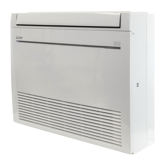
INDOOR UNIT
INDOOR UNIT
SERVICE MANUAL
Models
MFZ-KJ09NA
MFZ-KJ12NA
MFZ-KJ15NA
MFZ-KJ18NA
NOTE:
• This service manual describes technical data of the indoor units.
• RoHS compliant products have <G> mark on the spec name plate.
For servicing of RoHS compliant products, refer to the RoHS Parts List.
-
U1
-
U1
-
U1
-
U1
CONTENTS
1. TECHNICAL CHANGES ··································· 3
2. PART NAMES AND FUNCTIONS ····················· 4
3. SPECIFICATION ················································ 5
4. OUTLINES AND DIMENSIONS ························ 7
5. WIRING DIAGRAM ············································ 8
6. REFRIGERANT SYSTEM DIAGRAM ··············· 9
7. SERVICE FUNCTIONS ··································· 10
8. MICROPROCESSOR CONTROL ··················· 12
9. TROUBLESHOOTING ····································· 21
10. DISASSEMBLY INSTRUCTIONS ···················· 36
PARTS CATALOG (OBB752)
Revision B:
• 4. OUTLINES AND DIMENSIONS has been
modified.
OBH752 REVISED EDITION-A is void.
No. OBH752
REVISED EDITION-B
Outdoor unit service manual
MUFZ-KJ•NAHZ Series (OBH753)
MXZ-C•NA, MXZ-C•NAHZ Series
(OBH702, OCH573)
Advertisement
Table of Contents

Summarization of Contents
Part Names and Functions
Accessories
Lists and identifies included accessories for the indoor units.
Specifications
Single Connection Specifications
Details specifications for single indoor unit connections.
Multi Connection Specifications
Details specifications for multi-indoor unit connections.
Operating Range
Defines the operating voltage and temperature ranges for the unit.
Outlet Air Speed and Coverage
Provides data on airflow speed and coverage for different modes.
Service Functions
Timer Short Mode
Shortens the timer setting for service purposes.
Setting Remote Controller for Specific Unit
Guides on assigning remote controllers to specific indoor units.
Auto Restart Function
Explains the auto-restart feature and how to disable it.
Microprocessor Control
Wireless Remote Controller
Details the functions and buttons of the wireless remote controller.
Indoor Unit Display Section
Explains the meaning of the operation indicator lamp on the indoor unit.
Cool Operation
Describes how to operate the unit in COOL mode.
Dry Operation
Describes how to operate the unit in DRY mode.
Fan Operation
Explains the FAN mode operation where only the indoor fan runs.
Heat Operation
Describes how to operate the unit in HEAT mode.
Auto Changeover and Auto Mode Operation
Explains automatic switching between COOL and HEAT modes.
Auto Vane Operation
Details the automatic horizontal vane movement and air outlet selection.
Timer Operation
Setting the Current Time
Instructions on setting the current time for timer functions.
Setting ON and OFF Timers
How to set the ON and OFF timers for scheduled operation.
Releasing Timer Settings
How to cancel active timer settings.
Weekly Timer Operation
Setting the Weekly Timer
Step-by-step guide to programming weekly timer schedules.
Sleep Operation
Setting Sleep Operation
Instructions for activating and configuring the sleep mode.
Smart Set Operation
Setting Smart Set Operation
How to configure custom preset operations.
Canceling Smart Set Operation
Steps to disable the Smart Set operation.
Emergency and Test Operation
Emergency/Test Operation Indicator
Explains the indicator lamp during emergency or test operations.
3-Minute Time Delay Operation
Describes the compressor protection time delay.
Changing Temperature Units
How to switch between Fahrenheit and Celsius temperature displays.
Troubleshooting
Troubleshooting Cautions and Procedures
Safety notes, general procedures, and battery replacement for troubleshooting.
Failure Mode Recall Function
How to recall and diagnose past error modes using function and flow chart.
Indoor Unit Failure Mode Table
Table detailing indoor unit error codes, symptoms, conditions, and remedies.
Troubleshooting Instruction Flow
Step-by-step guide to diagnose and resolve unit issues with indicator lamp codes.
Troubleshooting Check Table
Comprehensive table of symptoms, conditions, and remedies for faults.
Trouble Judgement Criteria of Main Parts
Criteria for diagnosing specific major components like thermistors and motors.
Troubleshooting Flow: Indoor Fan Motor
Flowchart for diagnosing indoor fan motor issues.
Troubleshooting Flow: Remote Controller and Boards
Flowchart for checking remote controller and electronic boards.
Troubleshooting Flow: Electronic Control Board and Fan Motor
Flowchart for diagnosing the electronic control board and fan motor.
Checking Miswiring and Serial Signal Error
Procedure to identify and fix miswiring or serial signal errors.
LED Communication Status Indication
Explains LED indicators for communication status on the outdoor control P.C. board.
Electromagnetic Noise Troubleshooting
Steps to diagnose and mitigate electromagnetic interference issues.
Test Point Diagram and Voltage
Diagram showing test points and voltages on the indoor control board for diagnostics.
Disassembly Instructions
Removing the Front Panel
Step-by-step guide to remove the unit's front panel.
Removing the Electrical Box
Instructions for removing the electrical box assembly.
Removing Control Boards
Steps to remove the electronic control and display receiver P.C. boards.
Removing the Nozzle Assembly
Instructions for removing the nozzle assembly.
Removing Vanes
Guide on removing multi-flow and horizontal vanes.
Removing Horizontal Vane Motor
Steps for removing the horizontal vane motor.
Removing Multi-flow Vane Motor Unit
Instructions for removing the multi-flow vane motor unit.
Removing Fan Components
Steps for removing the line flow fan and indoor fan motor.


Need help?
Do you have a question about the MFZ-KJ09NA- U1 and is the answer not in the manual?
Questions and answers