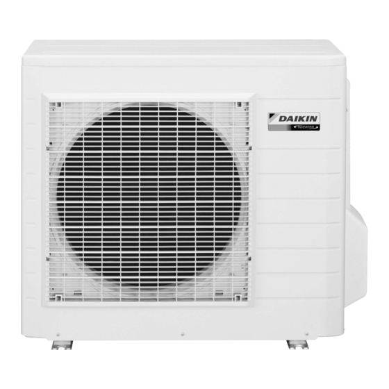
Summarization of Contents
Daikin Outdoor Unit Removal of Outer Panels
Remove Top Panel
Remove the 4 screws and lift the top panel.
Remove Discharge Grille
Remove the 4 screws and remove the discharge grille.
Remove Front Panel
Remove the 6 screws of the front panel.
Unfasten Shield Plate Hooks
Push front panel, lift shield plate to unfasten hooks.
Remove Front Panel (Hooks)
Unfasten side hooks, then remove the front panel.
Remove Stop Valve Cover
Remove screw and pull cover downward to unfasten hooks.
Daikin Outdoor Unit Removal of Outdoor Fan and Fan Motor
Remove Electrical Box Cover
Remove shield plate screw, unfasten electrical box cover hooks.
Disconnect Fan Motor Connector
Disconnect the connector for the fan motor [S70].
Release Fan Motor Lead Wire
Release the fan motor lead wire from the 7 hooks.
Remove Fan Motor Nut
Remove the M6 nut securing the outdoor fan.
Remove Fan Motor Screws
Remove the 2 lower screws, then the 2 upper screws from the fan motor.
Pull Out Fan Motor
Release fan motor lead wire and pull the fan motor out.
Daikin Outdoor Unit Removal of Electrical Box
Remove Shield Plate
Remove 2 screws, slide shield plate upward to unfasten hook.
Disconnect Power and Earth Wires
Remove terminal board screws, disconnect power and earth wires.
Remove Right Side Panel
Remove 3 screws and unfasten hooks of the right side panel.
Remove Electrical Box Screw
Remove the screw securing the electrical box.
Disconnect Front Side Connectors
Disconnect connectors [S40],[S20],[S90],[S80] from the front side.
Disconnect Compressor Relay Connector
Disconnect the relay connector for the compressor.
Release Thermistor Lead Wires Clamp
Release clamp, detach thermistor lead wires from hook.
Lift and Remove Electrical Box
Lift and remove the electrical box assembly.
Daikin Outdoor Unit Removal of PCBs
Disconnect Service Monitor PCB Connectors
Disconnect connectors [S52] and [S102] from the service monitor PCB.
Remove Service Monitor PCB
Detach 4 clamps with pliers and remove the service monitor PCB.
Remove Terminal Board Screws
Remove screws of the terminal board and the earth wire.
Open Terminal Board
Unfasten hook on right, then open the terminal board.
Disconnect Standby Saving Connector
Pull out standby electricity saving relay connector from terminal board.
Disconnect Reactor Connectors
Disconnect the 2 connectors for the reactor [HR1] [HR2].
Remove Main PCB Screws
Remove the 3 screws of the main PCB.
Daikin Outdoor Unit Removal of Sound Blankets and Thermistors
Remove Top Upper Sound Blanket
Remove the sound blanket (top upper).
Remove Top Lower Sound Blanket
Remove the sound blanket (top lower).
Remove Back Sound Blanket
Remove the sound blanket (back).
Remove Outer Sound Blanket
Remove the sound blanket (outer).
Remove Inner Sound Blanket
Remove the sound blanket (inner).
Release Discharge Pipe Thermistor
Release the discharge pipe thermistor.
Daikin Outdoor Unit Removal of Four Way Valve
Remove Four Way Valve Coil
Remove the screw and remove the four way valve coil.
Disconnect Four Way Valve
Heat up brazed part of the four way valve and disconnect.
Daikin Outdoor Unit Removal of Electronic Expansion Valve
Pull Out Expansion Valve Coil
Pull out the electronic expansion valve coil.
Remove Putty Sheets
Remove the sheets of putty.
Heat and Remove Expansion Valve
Heat 2 brazed parts of the electronic expansion valve and remove it.
Daikin Outdoor Unit Removal of Compressor
Remove Compressor Terminal Cover
Remove the terminal cover of the compressor.
Disconnect Compressor Lead Wires
Disconnect the lead wires of the compressor.
Release Compressor Lead Wires Clamp
Release clamp with pliers to detach compressor lead wires.
Remove Compressor Putty
Remove the putty from the compressor.
Remove Compressor Nuts
Remove the 2 nuts securing the compressor.
Disconnect Discharge Side Brazed Part
Heat discharge side brazed part and disconnect.
Disconnect Suction Side Brazed Part
Heat suction side brazed part and disconnect.
Lift and Remove Compressor
Lift the compressor up and remove it.


Need help?
Do you have a question about the RKS60GVMG and is the answer not in the manual?
Questions and answers