Table of Contents

Related Manuals for Toshiba HWS-G1901ENXR-E


Summarization of Contents
Safety Precautions and Product Overview
Introduction to the Service Manual
Manual's aim and scope for service engineers.
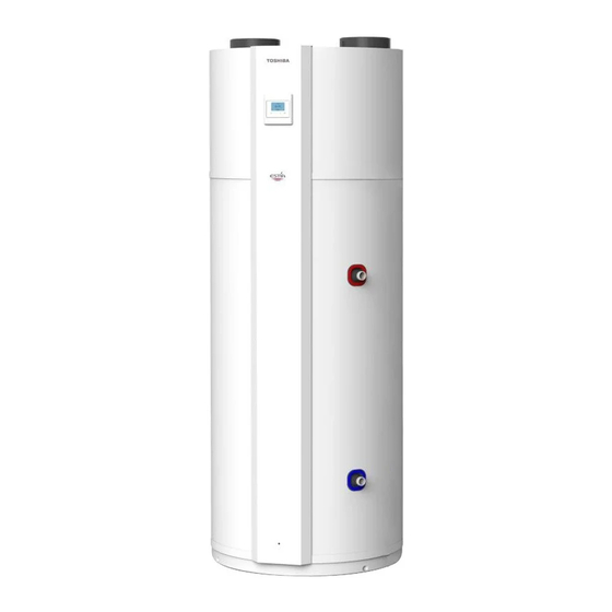
About the Domestic Hot Water Heat Pump
Product description based on EU directives.
General Components of the DHW-HP
Components of the domestic hot water heat pump.
DHW-HP Operation Modes
How the DHW-HP heats water using heat pump or electric heater.
Specifications of the DHW-HP
Physical Data and Dimensions
Technical dimensions and weight of the unit.
Performance Data and Efficiency
Key performance metrics like COP and heat-up times.
DHW-HP Technical Drawings
Dimensional Data Table
Table of physical dimensions of the unit.
Wiring Diagrams and Schematics
PC Board and Connection Layout
Details PCB layout and terminal connections.
System Electrical Schematic
Electrical schematic of the DHW-HP system.
Key Electrical Component Ratings
Refrigeration Component Ratings
Ratings for refrigeration system components.
Electrical Component Ratings
Ratings for electrical components like heater.
Sensor Specifications and Ratings
Ratings and specifications for temperature sensors.
System Diagrams
Refrigerant Cycle Diagram
Diagram and explanation of the refrigerant flow.
Water System Cycle Diagram
Diagram and explanation of the water circuits.
Detailed Operational Descriptions
P1 AUTO Mode Operation
Standard operation mode for heating water.
P2 ECO Mode Operation
Energy-saving mode for heating water.
P3 BOOST Mode Operation
Heating with heat pump and electric heater.
P4 BACKUP Mode Operation
Emergency heating mode using electric heater.
P5 SILENT Mode Operation
Reduced fan speed for quiet operation.
P6 HOLIDAY Mode Operation
Mode to turn off heating except for Legionella control.
B4 Hot on Time Function
Program unit to deliver hot water for a set duration.
B3 Low Tariff Function
Utilizes low electricity prices for heating.
B1 Ventilation Function
Controls fan for air circulation or external venting.
B5 Photovoltaic Function
Controls operation using solar PV signals.
PV ECO Operation in AUTO Mode
PV ECO mode behavior in AUTO mode.
PV ECO Operation in BOOST Mode
PV ECO mode behavior in BOOST mode.
PV Storage Operation in BOOST Mode
PV STORAGE mode behavior in BOOST mode.
D26 Extra Function Configuration
Enables Solar, Floor, or Cooling functions.
B6 Solar Function Operation
Operation of the solar heating function.
B7 Floor / B8 Floor T Function
Controls floor heating function.
B9 Cooling / B10 Cooling T Function
Controls cooling function via damper.
D27 SG Ready Function
Integrates with smart grid for energy management.
D29 External Control for Ventilation
Manages ventilation via external 0-10V input.
Defrost Operation Procedure
Automatic operation to remove ice from the evaporator.
Legionella Operation Cycle
Weekly cycle to prevent bacteria growth.
Modbus Communication Protocol
Modbus Communication Overview
Overview of Modbus communication capabilities.
Monitoring Functions via Modbus
List of parameters available for monitoring via Modbus.
Read and Write Functions via Modbus
Parameters that can be read or written via Modbus.
Method of Defect Analysis and Troubleshooting
Initial Checks Before Contacting Support
Initial checks before contacting support.
Check Power Supply Voltage
Verifies correct voltage supply to the unit.
Check Cold Water Supply
Ensures adequate cold water is available.
Operating in BACK-UP Mode During Errors
Procedure for using backup mode during errors.
Understanding Error Codes
List of error codes displayed on the controller.
Error Code Analysis and Solutions
Analysis of error codes and their possible causes/solutions.
Temperature Sensor Error Analysis
Diagnosing temperature sensor errors.
High Pressure Switch Error Analysis
Diagnosing high-pressure switch errors.
Evaporator Temperature Error Analysis
Diagnosing evaporator temperature errors.
High Evaporator Temperature Error Analysis
Diagnosing high evaporator temp errors.
Low Evaporator Temperature Error Analysis
Diagnosing low evaporator temp errors.
Filter Change Error Analysis
Diagnosing filter replacement errors.
Resetting Error Codes and Backup Mode
Procedure to reset errors and restore operation.
DHW-HP Settings and Configuration
Home View and Control Panel Navigation
Navigating the unit's control panel interface.
Information Menu Access and Data
Accessing operational data like temperatures, errors.
Mode of Operation Selection
Selecting different heating strategies for the unit.
Temperature Set Point Configuration
Setting temperature levels for different modes.
Additional Function Settings
Accessing additional operational features.
General Settings and Reset Function
Standard settings, including the reset function.
Installer Menu Parameters
Installer menu access and parameters.
Periodic Inspection and Maintenance
Environmental Requirements
Regulations for recycling and disposal.
Heating System and Fan Servicing
Servicing the evaporator and fan.
Condensation and Condensate Drain Cleaning
Cleaning the condensate drain.
Water Circulation and Tank Maintenance
Maintenance of water circulation components.
Pressure Relief Valve Maintenance
Testing and maintenance of the pressure relief valve.
Anode Inspection and Replacement
Inspecting and replacing the magnesium anode.
Part Exploded View and Parts List
Component Part Numbers and Descriptions
List of part numbers and descriptions.
Replacement of Major Parts
Opening and Removing the Front Panel
Step-by-step guide to remove the front panel.
Removing the Top Shell and Cover
Instructions to remove the top shell and cover.
Removing the Evaporator Housing
Steps to remove the evaporator housing.
Replacing the Heating Element
Procedure to replace the heating element.
Replacing Safety Breakers
Steps for replacing safety breakers.
Replacing the Anode
Procedure for replacing the anode.
Replacing the Solenoid Valve Coil
How to replace the solenoid valve coil.
Replacing the Fan Kit
Steps to replace the fan kit.
Replacing the BT1 Sensor
Procedure to replace the BT1 sensor.
Replacing the BT2 Sensor
Steps to replace the BT2 sensor.
Replacing the BT3 Sensor
Procedure to replace the BT3 sensor.
Replacing the BT4 Sensor
Steps to replace the BT4 sensor.
Replacing the Compressor
Procedure for replacing the compressor.
Replacing the Tube Kit
Steps to replace the tube kit.
Replacing PCB Boards (Standard & Deluxe)
Instructions for replacing PCB boards.
Replacing the Display and Frame
Procedure to replace the display and frame.
Need help?
Do you have a question about the HWS-G1901ENXR-E and is the answer not in the manual?
Questions and answers