Table of Contents
Advertisement
Quick Links
SERIAL NUMBERS
This manual applies directly to any swept CW generator with the
model and serial number prefix combination shown below. You
may have to modify this manual so that it applies directly to your
instrument version. Refer to the "Instrument History" chapter.
HP 83623L/3OL/4OL/5OL
3844A and below
HEWLETT
PACKARD
HP Part No. 08380-90134
Printed in USA
February 1999 Supersedes: September 1997
Advertisement
Chapters
Table of Contents

Related Manuals for HP HP 83640L


Summarization of Contents
Warranty
LIMITATION OF WARRANTY
Exclusions from warranty coverage, such as improper maintenance or misuse.
EXCLUSIVE REMEDIES
Buyer's sole remedies and disclaimer of incidental/consequential damages.
General Safety Considerations
WARNING
Safety warnings regarding operator-serviceable parts, fuses, and protective earthing.
HP 8360 L-Series Documentation
Documentation Map
Pictorial representation of the HP 8360 L-Series documentation.
Ordering Manuals
Information on ordering extra copies of the manual using part numbers.
Declaration of Conformity
Supplementary Information
Statement of compliance with Low Voltage and EMC directives, and CE marking.
Getting Started
Basic
Describes basic features of the swept CW generator for novice users.
Advanced
Covers special features for users familiar with swept CW generators.
Programming
Introduces SCPI language and analyzer programming for programming tasks.
CW Operation and Start/Stop Frequency Sweep
CW Operation
Describes producing a single, low-noise, synthesized frequency in CW mode.
Start/Stop Frequency Sweep
Explains sweeping between a selected start and stop frequency.
Power Level and Sweep Time Operation
Power Level Operation
Describes producing leveled power for CW, swept frequency, or power sweep operations.
Sweep Time Operation
Discusses varying sweep time and automatic sweep time selection.
Continuous, Single, and Manual Sweep Operation
Continuous sweep
Sweeps continuously retrace until a new mode is selected.
single sweep operation
Explains changing to single sweep mode and associated LED indications.
manual sweep mode
Describes manual sweep mode using rotary knob for adjustment.
Power Sweep and Power Slope Operation
Power Sweep Operation
Allows power output to be swept positively or negatively in CW frequency mode.
Power Slope Operation
Function for compensating system losses by linearly increasing power with frequency.
Advanced
Externally Leveling the Swept CW Generator
Describes operations where output power is detected externally for automatic adjustment.
Working with Mixers/Reverse Power Effects
Discusses issues and solutions related to working with mixers and reverse power effects.
Working with Spectrum Analyzers/Reverse Power Effects
Addresses reverse power issues with spectrum analyzers and unleveled modes.
Optimizing Swept CW Generator Performance
Demonstrates user flatness correction and methods to optimize performance.
Getting Started Programming
Modulation Commands
Notes that modulation commands are parsed but do not take action.
HP-IB General Information
Interconnecting Cables
Describes procedures and limitations for interconnecting instruments using HP-IB cables.
Instrument Addresses
Explains unique addresses for instruments in an HP-IB network.
HP-IB Instrument Nomenclature
Defines categories like listener, talker, and controller based on function.
Programming the Swept CW Generator
Describes controlling the generator via computer using HP-IB command statements.
HP-IB Command Statements
Abort
Command to terminate all listener/talker activity and prepare for new commands.
Getting Started with SCPI
Definitions of Terms
Defines key terms used in SCPI communication, including controller, instrument, and messages.
Standard Notation
Command Mnemonics
Explains long and short forms of commands, and case insensitivity.
Angle Brackets
Indicates words representing something other than themselves, like .
How to Use Examples
Command examples
Shows the format of command examples and how to type them in HP BASIC.
Essentials for Beginners
Program and Response Messages
Introduces basic types of messages sent between instruments and controllers.
Forgiving Listening and Precise Talking
Explains SCPI concepts of flexible command acceptance and precise response formatting.
Subsystem Command Trees
Paths Through the Command Tree
Explains how instruments interpret commands and how the parser determines the command tree path.
Subsystem Command Tables
Reading the Command Table
Explains how to read command tables, including root level commands and parameters.
More About Commands
Query and Event Commands
Explains commands that query values or cause actions, noting event commands are not queried.
Implied Commands
Describes commands assumed by the instrument if not explicitly sent.
Optional Parameters
Explains optional parameters and how the instrument chooses default values.
Parameter Types
Numeric Parameters
Used for settings requiring numbers, accepting decimal representations.
Extended Numeric Parameters
Used for physical quantities, accepting numeric and special values like MAX/MIN.
Response Data Types
Real Response Data
Decimal numbers in fixed or scientific notation, often handled transparently.
Example Programs
Example Program
Demonstrates how SCPI instruments work together for measurements.
Description
Describes a program measuring the linearity of a voltage controlled oscillator (VCO).
Program Listing
The actual BASIC code listing for the voltage controlled oscillator test.
Details of Commands and Responses
In This Subsection
Lists topics: program message syntax, response syntax, and SCPI data types.
Program Message Syntax
Examines SCPI program message construction, including commands and terminators.
General Status Register Model
Condition Register
Monitors hardware/firmware status in real time; read-only.
Transition Filter
Specifies bit state changes that set bits in the event register.
Event Register
Latches transition events from the condition register as specified by the transition filter.
Enable Register
Specifies bits in the event register that can generate a summary bit.
An Example Sequence
Illustrates the response of a single bit position in a status group.
Programming the Trigger System
Generalized Trigger Model
Explains the structure and components of the layered trigger model.
Common Trigger Configurations
Discusses the simplest trigger configurations: INIT and TRIG.
Trigger Command Definitions
Provides condensed definitions for keywords used in the trigger system subsection.
Details of Trigger States
Inside the Idle State
Illustrates the operation of the idle state and its transitions.
Inside the Initiate State
Illustrates the operation of the initiate state and its downward/upward paths.
Inside Event Detection States
Explains operation of event detection states and source commands.
SOURce
Selects the trigger source for an event-detection state, listing common sources.
IMMediate
Bypasses event detection, ECOunt, and DELay qualifications for one time.
Common Trigger Configurations
The INIT Configuration
The simplest trigger configuration, using only INITiate and ABORt subsystems.
Operating and Programming Reference
How To Use This Chapter
Explains how to use the chapter, referencing alphabetical entries and menu maps.
Address
Adrs Menu
Accesses the HP-IB address menu for controlling meter, generator, and printer addresses.
ALC
ALC BW Menu
Accesses the ALC bandwidth menu for selecting appropriate bandwidth.
Coupling Factor
Specifies coupling factor of external devices, showing power at coupler output.
Leveling Mode ALCoff
Disables ALC leveling circuits for direct control of modulator and attenuator.
Leveling Mode Normal
Sets continuous leveling at the specified leveling point, controlled by ALC loop.
Leveling Mode Search
Activates power search leveling, automatically finding correct modulator setting.
Leveling Point ExtDet
Sets generator to level power externally via negative detector output.
Leveling Point Internal
Sets generator to level power internally using its internal detector.
Leveling Point Module
Sets generator to level power at the output of a millimeter-wave source module.
Leveling Point PwrMtr
Sets generator to level power at an external power meter via recorder output.
Internal Leveling - Leveling Mode Normal, Leveling Point Intrnl
Coupled Operation
How power output is achieved using step attenuator and ALC, especially for levels below -20 dBm.
Uncoupled Operation
Controls ALC level and attenuator separately for specific applications like power sweep.
CONNECTORS
BNC Connectors
Describes AUX OUTPUT, EXT ALC, SWEEP OUTPUT, STOP SWEEP IN/OUT connectors.
Dblr Amp Menu
Doubler Amp Mode AUTO
Sets the doubler amplifier mode to AUTO, default for specified performance.
Doubler Amp Mode On
Turns the doubler amplifier on regardless of frequency, unspecified performance.
Doubler amp Mode Off
Turns the doubler amplifier off regardless of frequency, unspecified performance.
Delete Menu
Delete All
Deletes the complete array for frequency list or power flatness.
Delete Current
Deletes the active line in the array (frequency entry or correction value).
Delete Undef
Deletes undefined correction values in the power flatness menu.
Fault Menu
Fault Info 1
Displays latched status of PEAK, TRACK, RAMP, SPAN, V/GHZ, and ADC fault messages.
Fault Info 2
Displays latched status of EEROM, PWRON, CALCO, PLLZERO, PLLWAIT, and FNXFER fault messages.
Fault Info 3
Displays latched status of CALYO, CALMAN, TMR CNFLCT, and SEARCH fault messages.
Clear Fault
Clears all latched fault status messages.
Fltness Menu
Auto Fill Incr
Creates a frequency list using a specified increment.
Auto Fill #Pts
Creates a frequency list containing a specified number of points.
Auto Fill Start
Sets the start frequency for the flatness correction array.
Auto Fill Stop
Sets the stop frequency for the flatness array.
Clear Point
Changes power correction value for a frequency point to undefined state.
Copy List
Copies frequency list into the frequency parameter of the flatness correction array.
CorPair Disable
Disables frequency-correction pair array, using HP-IB transferred set.
Delete Menu
Reveals the delete softkeys for frequency list and flatness.
Enter Corr
Enables entry of power correction value for a frequency point.
Enter Freq
Enables entry of a single frequency point into the flatness array.
Freq Follow
Sets generator to CW frequency mode for correction value entry.
Mtr Meas Menu
Reveals softkeys for the power meter measure correction menu.
Freq Cal Menu
Swp Span Cal Always
Performs sweep span calibration each time frequency span changes.
Swp Span Cal Once
Activates sweep span calibration immediately, performing it once.
FREQUENCY (MENU)
CW/CF Coupled
Couples CW function to center frequency; changes in one affect the other.
Freq Mult
Sets frequency multiplier value, applying it to all frequency parameters.
Freq Offset
Sets frequency offset value, applying it to all frequency parameters.
List Menu
Displays softkeys for frequency list creation and editing.
Step Swp Menu
Reveals stepped frequency sweep entry softkeys.
Up/Down Size CW
Sets frequency step size in CW frequency mode.
Up/Down Size Swept
Sets frequency step size in the swept frequency step mode.
zoom
Activates CF/Span sweep mode for controlled center frequency and span adjustment.
HP-IB Address
HP-IB Menu
Reveals softkeys for HP-IB control, including address and language settings.
Adrs Menu
Reveals softkeys that allow HP-IB addresses to be changed.
Programming Language Analyzr
Selects Analyzer Language for HP network analyzer compatibility.
Programming Language CIIL
Selects CIIL as the external interface language, requiring Option 700.
Programming Language SCPI
Selects SCPI as the default external interface language, common across HP products.
List Menu
Auto Fill Incr
Creates a frequency list using a user-specified increment.
Auto Fill #Pts
Creates a frequency list with a user-specified number of points.
Auto Fill Start
Allows entry of a start frequency for the frequency list.
Auto Fill Stop
Allows entry of a stop frequency for the frequency list.
Delete Menu
Reveals the frequency list delete menu.
Enter List Dwell
Allows entry of a dwell time for a frequency point in the frequency list.
Enter List Freq
Allows entry of a frequency point into the frequency list.
Enter List Power
Allows entry of an ALC output power correction value for a frequency.
Global Dwell
Sets dwell time for all points in the frequency list to a user-specified value.
Global Offset
Sets ALC output power correction value for all points in the frequency list.
Pt Trig Menu
Reveals the frequency list in the point trigger menu.
MARKER
Ampl Markers
Displays markers as amplitude spikes, allowing amplitude variation.
Center=Marker
Changes center frequency to the value of the most recently activated marker.
Delta Marker
Displays frequency difference between two markers.
Delta Mkr Ref
Reveals softkeys in the delta marker reference menu.
Ml--M2 Sweep
Causes generator to sweep from marker Ml frequency to M2 frequency.
Marker Ml
Turns marker Ml on/off and sets its frequency value.
Marker M2
Turns marker M2 on/off and sets its frequency value.
Marker M3
Turns marker M3 on/off and sets its frequency value.
Marker M4
Turns marker M4 on/off and sets its frequency value.
Marker M5
Turns marker M5 on/off and sets its frequency value.
Markers All Off
Turns all markers off simultaneously.
Start=Ml Stop=MZ
Changes start frequency to marker Ml and stop frequency to marker M2.
Module Menu
Module Select AUTO
Sets automatic selection of the millimeter source module interface connector.
Module Select Front
Examines only the front panel connector to determine source module type.
Module Select None
Disables millimeter source module sensing, preventing alteration of frequency limits or multiplier.
Mtr Meas Menu
Meas Corr All
Measures flatness correction values for all frequency points in the array.
Meas Corr Current
Measures correction value for the current frequency point in the active line.
Meas Corr Undef
Measures correction values for frequency points without assigned values.
POWER LEVEL
Normal, Internal
Controls output power directly, with attenuator coupled to ALC for full range.
Normal, Uncoupled Attenuator
Controls Level DAC and Level Control Circuits independently of attenuator.
Normal, External Detector (ExtDet)
Controls output power based on external detector feedback, uncoupling attenuator.
Normal, Power Meter (PwrMtr)
Controls output power based on power meter feedback, using restricted ALC range.
POWER (MENU)
Fitness Menu
Accesses softkeys in the flatness correction menu.
Power Offset
Changes displayed power to include an offset without altering output power.
Power Slope
Activates linear, power-per-frequency mode, making RF slope active.
Power Sweep
Activates power sweep mode, making power sweep (dB/swp) active.
Set Atten
Activates uncoupled attenuator operation, making attenuator value active.
Tracking Menu
Accesses softkeys in the tracking calibration menu.
Uncoupl Atten
Uncouples the attenuator from the ALC system.
Up/Dn Power
Allows entering values for power level step size.
SCPI COMMAND SUMMARY
IEEE 488.2 Common Commands
Lists common commands like CLS, ESE, ESR, IDN, LRN, OPC, OPC?, RST.
Security Menu
Blank Display
Turns off generator's display, active entry, and message line areas.
Clear Memory
Returns generator to factory preset state by overwriting state functions.
Save Lock
Disables the save function, prohibiting saving instrument state.
Zero Freq
Displays zeros for all accessible frequency information.
Step Swp Menu
Dwell Coupled
Couples dwell time for stepped sweep points to ramp sweep time.
Step Control Master
Designates generator as master control in a dual system.
Step Control Slave
Designates generator as slave in a dual system.
Step Dwell
Sets dwell time for points in stepped sweep.
Step Points
Sets the number of points in a stepped sweep.
Step Size
Sets the increment value for points in a stepped sweep.
Step Sap Pt Trig Auto
Automatically steps generator to next point in stepped sweep.
Step Sup Pt Trig Bus
Steps generator to next point via HP-IB trigger in sweep list mode.
Step Swp Pt Trig Ext
Steps generator to next point via external hardware trigger in sweep list mode.
SWEEP (MENU)
Manual Sweep
Activates manual sweep mode, allowing manual adjustment of parameters.
Start Sweep Trigger Auto
Automatically triggers sweep when SINGLE or CONT is pressed.
Start Sweep Trigger Bus
Waits for HP-IB trigger when SINGLE or CONT is pressed.
Start Sweep Trigger Ext
Waits for external hardware trigger when SINGLE or CONT is pressed.
Sweep Mode List
Activates step frequency list mode, stepping only through defined list frequencies.
Sweep Mode Ramp
Activates analog frequency sweep mode; ramp sweep is factory preset.
Sweep Mode Step
Activates stepped frequency step mode for manual, continuous, or single sweeps.
SwpTime Auto
Sets sweep time to minimum value for a chosen span, meeting specifications.
TrigOut Delay
Specifies time delay after phase-lock before trigger pulse is sent.
SYSTEM (MENU)
Alternate Regs
Alternates sweeps between present and stored instrument states.
Dim Display
Dims the swept CW generator's display.
Disp Status
Displays the present status of the swept CW generator.
HP-IB Menu
Reveals the HP-IB control menu.
Preset Mode Factory
Sets the preset state to factory defaults for the PRESET key.
Preset Mode User
Sets the preset state to user-defined conditions for the PRESET key.
Ref Osc Menu
Reveals the frequency standard options menu.
Save User Preset
Stores the present instrument state in a special preset storage register.
Security Menu
Reveals the menu controlling security features of the swept CW generator.
Software Rev
Causes generator to display the date code of its internal software.
UsrKey Clear
Activates USER-DEFINED menu and allows deletion of single keys.
Tracking Menu
Auto Track
Realigns output filter and oscillator to maximize power for swept frequency mode.
Peak RF Always
Periodically realigns output filter and oscillator for CW mode.
Peak RF Once
Realigns output filter and oscillator to maximize power for CW mode.
USER CAL
FullUsr Cal
Performs a complete alignment determined by instrument settings.
Tracking Menu
Accesses the softkeys of the tracking menu.
Freq Cal Menu
Accesses the Frequency span calibration menu.
Ext Det Cal
Uses external power meter to calibrate external detector's output voltage.
Error Messages
Introduction
Lists front panel or bus transmitted error messages with explanations and suggestions.
Front Panel Error Messages in Alphabetical Order
Alphabetical list of error messages with explanations and potential causes.
Frequency
Range
Lists frequency ranges for different HP 8360 models.
Resolution
Specifies standard and option 008 resolution.
Frequency Bands (for CW signals)
Lists frequency bands and corresponding 'n' values for CW signals.
Frequency Modes:
Details accuracy for CW and Manual Sweep modes.
Switching Time
Defines switching times for steps within bands and across bands.
RF Output
Output Power
Specifies maximum leveled and minimum settable output power for different models and frequencies.
Spectral Purity
Spurious Signals
Specifies harmonic and subharmonic spurious signal levels.
Single-Sideband Phase Noise (dBc/Hz)
Offset from Carrier
Provides single-sideband phase noise values at various offset frequencies.
General
Environmental
Specifies operating temperature, altitude, humidity, and enclosure protection.
Warmup Time
Details required warm-up time for instrument and frequency reference.
Power Requirements
Specifies voltage, frequency, and VA requirements.
Weight & Dimensions
Provides net weight, shipping weight, and physical dimensions.
Adapters Supplied
Lists adapter types and part numbers supplied with models.
Inputs & Outputs
Auxiliary Output
Provides unmodulated reference signal with typical minimum power level and impedance.
RF Output
Specifies nominal output impedance and connector type.
External ALC Input
Used for negative external detector or power meter leveling.
Trigger Input
Activated on TTL rising edge for external initiation of analog sweep or list advance.
Trigger Output
Outputs TTL-level pulses for analog sweep or step/list mode points.
30 MHz Reference Input
Accepts 10 MHz reference signal for operation from external time base.
10 MHz Reference Output
Provides 0 dBm, 10 MHz signal from internal frequency standard.
Sweep Output
Supplies voltage proportional to sweep, with accuracy specifications.
Stop Sweep Input/Output
Stops sweep when grounded externally; resumes when TTL-high.
Options
Option 001 Add Step Attenuator
Adds step attenuator, lowering minimum settable output power.
Option 004 Rear Panel RF Output
Moves RF Output and other connectors to the rear panel.
Option 008 1 Hz Frequency Resolution
Provides frequency resolution of 1 Hz.
Option 700 MATE System Compatibility
Provides CIIL programming commands for MATE system compatibility.
Installation
CAUTION
Product designed for Installation Category II and Pollution Degree 2.
Initial Inspection
Inspect shipping container for damage and check contents for completeness.
Equipment Supplied
Table 3-1. Adapter Descriptions and Part Numbers Shipped with Each Swept CW Generator Model
Table listing adapter descriptions and part numbers for each model.
Preparation for Use
Enclosure Protection
Position instrument according to enclosure protection, not against water ingress.
Power Requirements
Specifies power source requirements: voltage, frequency, and VA consumption.
Line Voltage and Fuse Selection
Match voltage selector and fuse to site's AC line voltage before connecting power.
Language Selection
How to View or Change a Language Selection from the Front Panel
Sets programming language via front panel and rear panel HP-IB switch.
How to Select a Language on a Swept CW Generator without a Front Panel
Sets rear panel HP-IB switch for desired language if no front panel is present.
HP-IB Address Selection
Table 3-3. Factory-Set HP-IB Addresses
Table listing factory-set HP-IB addresses for instruments.
How to View or Change an HP-IB Address from the Front Panel
How to Prevent a Front Panel Change to an HP-IB Address
Disables address softkeys by setting rear panel HP-IB switch to any address other than 31.
How to Set the HP-IB Address on a Swept CW Generator without a Front Panel
Sets the rear panel HP-IB switch to the desired address if no front panel is available.
Operating Environment
CAUTION
Ensure airflow passages are clear before installing in operating environment.
Chassis Kits
Rack Mount Slide Kit (Option 806)
Supplies rack mount slides and hardware to install instrument on swept CW generator.
Table 3-4. Rack Mount Slide Kit Contents
Table itemizing parts included in the rack mount slide kit.
CAUTION
Ventilation requirements for cabinet installation to prevent overheating.
Rack Flange Kit for Swept CW Generators with Handles Removed (Option 908)
Table 3-5. Rack Flange Kit for Swept CW Generators with Handles Removed Contents
Table itemizing parts in kit for rack mounting without front handles.
CAUTION
Ventilation requirements for cabinet installation to prevent overheating.
Rack Flange Kit for Swept CW Generators with Handles Attached (Option 913)
Table 3-6. Rack Flange Kit for Swept CW Generators with Handles Attached Contents
Table itemizing parts in kit for rack mounting with front handles.
CAUTION
Ventilation requirements for cabinet installation to prevent overheating.
Storage and Shipment
Environment
Specifies storage and shipping limits for temperature, humidity, and altitude.
Package the Swept CW Generator for Shipment
CAUTION
Avoid using specified packaging materials like styrene pellets to prevent damage.
Converting HP 8340/41 Systems to HP 8360 L-Series Systems
Manual operation topics are:
Topics include functional compatibility, front panel operation, preset conditions, and connections.
Remote operation topics are:
Topics include language compatibility, status structure, and programming languages.
Manual Operation
Compatibility
HP 8360 L-Series is a superset of HP 8340/8341, with omissions like line triggers.
Front Panel Operation
HP 8360 L-Series uses softkey menu-driven approach vs. front panel key sequence.
Instrument Preset Conditions.
Factory presets are identical to HP 8340/8341; user can define custom presets.
System Connections
The HP 8510 Network Analyzer
Compatibility with HP 8510 network analyzer; describes connections and language configuration.
The HP 8757C/E Scalar Network Analyzer
Connections similar to HP 8340/8341, differs in modulator drive signal connection.
The HP 83550 Series Millimeter-wave Source Modules
Refer to 'Leveling with MM-wave Source Modules' for information.
The HP 8970B Noise Figure Meter
Connections identical to HP 8340/8341; configure address and language.
Remote Operation
Language Compatibility
Supports three HP-IB languages: Network Analyzer, SCPI, and CIIL.
Network Analyzer Language
Identical syntax to HP 8340/8341, but differences prevent successful program execution.
Test and Measurement System Language
SCPI language developed by HP for controlling instruments, conforming to IEEE 488.2.
Control Interface Intermediate Language
Instrument control language for Option 700 HP 8360 L-Series, M.A.T.E.-compatible.
Converting from Network Analyzer Language to SCPI
Illustrates programming commands in Network Analyzer and SCPI.
Numeric Suffixes
Table 3-8. Numeric Suffixes
Table listing numeric suffixes for Network Analyzer and SCPI languages.
Operator’s Check and Routine Maintenance
WARNING
No operator serviceable parts inside. Refer servicing to qualified personnel.
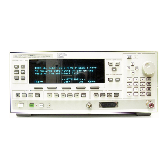
Operator’s Checks
Allows operator to make a quick check of main generator functions prior to use.
Service Information
Contact qualified technician if maintenance procedures do not clear problem.
Local Operator’s Check
Description
Provides assurance that internal functions are working; no external equipment needed.
Preliminary Check
Checks internal CPU, power supplies, and front panel after power on or preset.
Routine Maintenance
WARNING
Replace line fuse only with same type and rating for fire protection.
How to Replace the Line Fuse
Step-by-step instructions for replacing the line fuse.
Note
Detachable power cord is the disconnecting device; front panel switch is standby.
How to Clean the Fan Filter
CAUTION
Ensure airflow passages are clear before installing in operating environment.
How to Clean the Cabinet
WARNING
Disconnect from mains before cleaning to prevent electrical shock.
Need help?
Do you have a question about the HP 83640L and is the answer not in the manual?
Questions and answers