
Related Manuals for Danfoss TT350 Series


Summarization of Contents
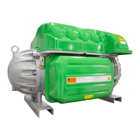
Introduction to Danfoss Turbocor Compressors
Scope of the Manual
Manual is for application/installation of Danfoss Turbocor compressors.
Manual Organization Overview
Manual is divided into sections: Overview, Compressor Module, System Design, Installation.
Document Symbols Explained
Explains symbols used (Danger, Warning, Caution, Note).
Glossary of Technical Terms
Glossary of terms and acronyms used in the manual.
Overview of TT/TG Series Compressors
TT/TG Compressor Nomenclature Guide
Explains the coding system for TT/TG compressor models.
Refrigerant Type Compatibility
Details refrigerants used for TT and TG series compressors.
Environmental Operating Conditions
Specifies storage and operation ambient temperature and humidity limits.
TT/TG Compressor Model Configurations
Describes the TT/TG compressor, motor, and power assemblies.
Compressor Module Components
Provides an overview of the compressor's aerodynamics, motor, and electronics.
Functional Description of Turbocor Compressors
Main Refrigerant Fluid Path
Describes refrigerant flow from intake to discharge port via impellers and diffusers.
Motor and Component Cooling System
Explains how liquid refrigerant cools compressor components.
Inlet Guide Vane (IGV) Operation
Details the IGV assembly for capacity control and vane angle adjustment.
Compressor Control System Overview
Shows a functional block diagram of the compressor control system.
Motor Drive System Operation
Describes AC power conversion to variable frequency AC for motor operation.
Soft-Start Board Functionality
Limits inrush current during compressor startup.
Bearing Motor Compressor Controller (BMCC)
Central processor for compressor control, bearing and motor management.
Compressor Operational Control Logic
Continuously monitors status and responds to changing conditions for optimal performance.
Compressor Capacity Modulation
Controls motor speed and IGV position to meet load requirements and avoid surge.
Electronic Expansion Valve (EXV) Control
Details the on-board EXV driver and its manual control for capacity.
Motor and Magnetic Bearing Control Systems
Explains magnetic bearing system support and controller feedback.
Compressor Monitoring Functions
Lists parameters monitored by the compressor controller (>60).
Handling Abnormal Operating Conditions
Describes how the controller responds to abnormal operating conditions.
Bearing PWM Amplifier Function
Supplies current to magnetic bearing actuators using PWM signals.
Serial Driver Module Operation
Performs serial-to-parallel conversion for stepper motor drive signals.
Backplane Interconnectivity and Power
Interconnects modules and has DC-DC converters and status LEDs.
High-Voltage DC-DC Converter Function
Supplies and isolates high/low DC voltages for control circuits.
Magnetic Bearing System Operation
Details the five-axis bearing system for shaft levitation.
Control Interface Wiring and Connections
Typical Control Wiring Diagram
Shows wiring connections for the compressor I/O board from the chiller.
Modbus Grounding Diagram
Illustrates grounding connections for Modbus communication.
Control Wiring Best Practices
Provides guidelines for proper control wiring techniques.
General Compressor Specifications
Construction Materials and Design
Details materials and design of compressor components.
Maximum Operating Pressure Limits
Defines regulated operating pressure limits (Alarm, Trip, Ratio).
Maximum Discharge Temperature Limits
Specifies temperature limits for compressor operation.
Suction Pressure Limits and Settings
Displays suction pressure alarm and trip limits for models.
Codes and Standards Compliance
Outlines OEM responsibility for safety and compliance.
Electrical Specifications and Requirements
Acceptable Supply Voltage and Frequency
Specifies acceptable voltage and frequency ranges for operation.
Compressor Current Limit Settings
Details FLA/LRA settings and configuration for current limits.
Required Input Disconnects
Requires input disconnect per codes for full-load current protection.
AC Input Line Protection
Mandates fast-acting fuses for protection of power electronics.
CE Compliance and EMI/EMC Filtering
Addresses EMI/EMC filtering requirements for CE compliance.
Grounding Connection Guidelines
Provides guidelines for proper grounding of electrical connections.
Mains Input Cable Specifications
Advises using shielded cable for mains input and specifies ratings.
Compressor Performance Characteristics
Performance Ratings Explained
Explains how capacity, efficiency vary with conditions.
Performance Tolerance Guidelines
Defines acceptable tolerance bands for compressor performance.
Operating Envelopes for TT/TG Series
TT300 and TG230 Operating Envelope
Shows operating limits for TT300 and TG230 compressors.
Medium Temp TT300/TG230 Envelope
Illustrates operating limits for medium temp TT300/TG230.
TT350 and TG310 Operating Envelope
Presents operating limits for TT350 and TG310 compressors.
TT400 and TG390 Operating Envelope
Details operating limits for TT400 and TG390 compressors.
TT700 and TG520 Operating Envelope
Shows operating limits for TT700 and TG520 compressors.
Guide Specifications for System Design
General Construction Specifications
Describes the two-stage, variable-speed compressor design and construction.
Refrigerant Specifications
Specifies refrigerants for TT (R134a) and TG (R1234ze(E)) compressors.
Compressor Bearing System
Details radial, axial magnetic bearings for shaft levitation.
Capacity Control Mechanisms
Explains VFD for modulation, IGVs for low load trim.
Compressor Motor Features
Describes direct-drive, permanent-magnet synchronous motor.
Compressor Electronics and Control
Covers microprocessor controller for bearings and speed control.
Recommended Ancillary Devices
Recommends check valve and line reactor for discharge port protection.
System Design Guidelines
General Design Requirements
Covers installation, operating, envelope, capacity, piping, cleaning and control.
Economizer Option Benefits
Explains advantages of economizer for efficiency and capacity.
Motor/Electronics Cooling Requirements
Details requirements for motor/electronics cooling liquid feed.
Sample Refrigeration Circuits
Typical Refrigeration Piping Schematic
Shows a typical refrigeration piping schematic with components.
Piping Schematic with Staging/Load Balancing
Illustrates piping with staging and load balancing valves.
Refrigeration Schematic with Flash Tank Economizer
Shows a refrigeration circuit with a flash tank economizer.
Refrigeration Schematic with Sub-Cooler Economizer
Depicts a circuit with a sub-cooler circuit economizer.
Refrigeration Schematic with Motor Cooling PRV
Illustrates piping with motor cooling PRV for medium temp units.
Refrigeration Schematic with Multiple DX Evaporators
Shows a schematic for multiple DX evaporators.
Refrigeration Schematic with Multiple Compressors
Illustrates multiple compressors with a flooded evaporator.
Sound and Power Specifications
TT300/TT400 Sound Power Measurements
Details sound power measurements for TT300/TT400 compressors.
Sound Measurement Results Summary
Presents sound power and pressure calculation results.
TT300 Sound Power Data
Provides sound power data for TT300 at different operation modes.
TT300 Sound Pressure Calculation
Shows sound pressure calculations for TT300 at various distances.
Physical Data and Dimensions
Required Service Clearances
Specifies required service and maintenance clearances around the compressor.
Center of Gravity Information
Provides diagrams and coordinates for the compressor's center of gravity.
Discharge Port Details
Shows dimensional details of discharge ports for various models.
Suction Port Dimensions (All Models)
Illustrates suction port details for all models.
Flange Footprint Details
Provides flange footprint dimensions for various models.
Component Torque Specifications
Provides torque values for various compressor components.
Environmental Considerations
Humidity Impact and Mitigation
Discusses insulation and drip trays for humid environments.
Vibration Transfer Minimization
Recommends bracing external copper piping to minimize vibration.
Shipping Considerations
Transit Vibration Protection
Suggests anti-vibration bracket for motor cooling line during transit.
Installation Procedures
Unpacking and Initial Inspection
Details inspection for damage and reporting procedures.
Rigging and Handling Guidelines
Provides guidelines for safe rigging and handling of the compressor.
Compressor Unit Placement
Covers mounting, isolation pads, and leveling requirements.
Mounting Base Requirements
Specifies rigid surface mounting and isolation pad installation.
Piping Connection Procedures
Details attaching connections, soldering, and O-ring installation.
Compressor Control Wiring
Explains I/O board communication and connection to external equipment.
I/O Board Connection Steps
Guides on connecting interface cable to the compressor I/O board.
Circuit Grounding for I/O Board
Highlights importance of proper grounding for I/O board and circuits.
Voltage-Free Contact Verification
Details testing of interlock terminals for voltage-free status.
Compressor Power Wiring
Describes connection of power wiring to the compressor.
Appendix A: Power Line Accessories Installation
Line Reactor Installation Instructions
Applies to line reactor kit installation in a main supply panel.
AC Line Cable Connection (From External Disconnect)
Provides steps for connecting AC line cable from disconnect to line reactor.
AC Line Cable Connection (to Compressor Terminal)
Details connecting AC line cable from line reactor to compressor.
Appendix B: Power Line Accessories Installation
EMI/EMC Filter Installation
Covers mounting and connection of EMI/EMC filters.
EMI/EMC Filter Line Side Connection
Instructs on connecting line wires to the filter's line side.
EMI/EMC Filter Load Side Connection
Details connecting load wires to the filter's load side.
Harmonic Filter Installation Notes
Refers to manufacturer instructions for harmonic filter installation.
Need help?
Do you have a question about the TT350 Series and is the answer not in the manual?
Questions and answers