Table of Contents
Advertisement
TopPage
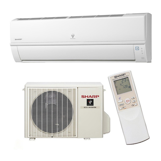
SPLIT TYPE
AIR CONDITIONER
[1]
SPECIFICATION .................................... . ....... 1-1
[2]
EXTERNAL DIMENSION....................... . ....... 1-3
[3]
WIRING DIAGRM .................................. . ....... 1-4
[4]
ELECTRICAL PARTS ............................ . ....... 1-5
[1]
BLOCK DIAGRAMS............................... . ....... 2-1
[2]
MICROCOMPUTER CONTROL SYSTEM.......... . ....... 2-3
[3]
FUNCTION............................................. . ....... 2-7
[1]
OPERATIONS ........................................ . ....... 3-1
[2]
THERMISTOR ERROR ......................... . ....... 3-3
[3]
CHARACTERISTICS ............................. . ....... 3-5
[4]
UNIT INDEPENDENTLY ........................ . ....... 3-5
[5]
GENERAL TROUBLESHOOTING CHART ......... . ....... 3-6
Parts marked with "
safety and performance of the set.
MODEL
INDOOR UNIT
AY-XP9LSR
AY-XP12LSR
" are important for maintaining the safety of the set. Be sure to replace these parts with specified ones for maintaining the
SERVICE MANUAL
In the interests of user-safety (Required by safety regulations in some countries) the set should
be restored to its original condition and only parts identical to those specified should be used.
CONTENTS
[6]
METHOD ......................................................3-8
[7]
OUTDOOR UNIT CHECK METHOD........... 3-11
[8]
TROUBLESHOOTING GUIDE ....................3-14
[9]
CHART ........................................................3-15
[1]
SCHEMATIC DIAGRAM ................................4-1
[2]
STANDARD CONDITION ..............................4-1
[3]
PRESSURE IN 3-WAY VALVE ......................4-1
[4]
PERFORMANCE CURVES...........................4-2
CHAPTER 5. DISASSEMBLING PROCEDURE
[1]
INDOOR UNIT...............................................5-1
[2]
(For the models with PLASMACLUSTER)..................5-4
[3]
DISASSEMBLY OF OUTDOOR UNIT...........5-5
No. S2005AYXP12LST
OUTDOOR UNIT
AE-X9LSR
AE-X12LSR
This document has been published to be used for
after sales service only.
The contents are subject to change without notice.
AYXP9LSR
Advertisement
Table of Contents
Troubleshooting

Related Manuals for Sharp Plasmacluster AY-XP12LSR


Summarization of Contents
Chapter 1: Specification Details
Specification Table
Detailed specifications for indoor and outdoor units, including capacities and electrical data.
External Dimensions
Visual representation of indoor and outdoor unit dimensions with measurements.
Wiring Diagrams
Electrical connection diagrams for indoor and outdoor units, including self-diagnosis.
Electrical Parts List
List of electrical components for indoor and outdoor units with model numbers.
Chapter 2: Circuit and Operation Explanation
Block Diagrams
Functional block diagrams of indoor and outdoor unit control systems.
Microcomputer Control System
Details electronic control circuits and interconnections for both units.
Function and Operation
Explains operational modes, protective functions, and circuit operations.
Chapter 3: Protective Procedures and Functions
Protective Device Functions
Describes safety features, detection, reset conditions, and error displays.
Thermistor Error Operations
Explains unit behavior and responses to thermistor malfunctions in various modes.
General Troubleshooting Chart
Lists common issues, inspection methods, and recommended remedies.
Chapter 4: Refrigeration Cycle
Schematic Diagram
Visual representation of the refrigerant circuit and its components.
Standard Conditions and Temperatures
Specifies operating conditions, temperatures, and pressures at various points.
Performance Curves
Illustrates performance characteristics like capacity and input power versus outdoor temperature.
Chapter 5: Disassembling Procedure
Indoor Unit Disassembly
Step-by-step guide for safely disassembling the indoor unit.
Plasmacluster Unit Removal
Instructions for removing the Plasmacluster unit from the indoor unit.
Outdoor Unit Disassembly
Step-by-step guide for safely disassembling the outdoor unit.
Malfunction (Parts) Check Method
Component Failure Diagnosis
Procedures for diagnosing faults in IPM, expansion valve, diodes, and capacitors.
Outdoor Unit Check Method
Checking Procedures
Steps to verify repair completion and perform final checks on the outdoor unit.
Troubleshooting Outdoor Electric Components
Guides on diagnosing issues with outdoor unit electric components and circuit boards.
Troubleshooting Guide
Self-Diagnosis Function
How to access and interpret the unit's self-diagnosis error codes via LEDs.
Malfunction Diagnosis Chart
Indications, Inspection Methods, and Remedies
Links malfunction codes, LED indicators, and remedies.
Need help?
Do you have a question about the Plasmacluster AY-XP12LSR and is the answer not in the manual?
Questions and answers