Table of Contents
Advertisement
AMS-150HD/ AMS-150HD-SSD/ AMS-150-SSD
AMS-300HD/ AMS-300HD-SSD/ AMS-300-SSD
NOTICE: The information contained within this manual is correct at time of printing, but due to the continuing development of prod ucts,
changes in specifications are inevitable. Ameri-Shred reserves the right to implement such changes without prior notice.
Service Department: 888.270.6879
OWNER'S MANUAL
SERIES 1 HARD DRIVE
Advertisement
Table of Contents

Related Manuals for Ameri-Shred AMS-150HD


Summary of Contents for Ameri-Shred AMS-150HD
- Page 1 NOTICE: The information contained within this manual is correct at time of printing, but due to the continuing development of prod ucts, changes in specifications are inevitable. Ameri-Shred reserves the right to implement such changes without prior notice. Service Department: 888.270.6879...
-
Page 2: Table Of Contents
TABLE OF CONTENTS UNLOADING/UNPACKING ......................... 3 ELECTRICAL INSTALLATION ........................4 NAMEPLATE (LOG SHREDDER SPECIFICS) ....................4 SAFETY WARNINGS ............................ 5 SHREDDER OPERATION ..........................6 START UP PROCEDURE ..........................7 SERVER DRIVE JAM WARNING ........................8 CLEARING A JAM ............................9 SHUT DOWN PROCEDURE ......................... -
Page 3: Unloading/Unpacking
NOTE: Series 1 Hard Drive Shredders are top heavy, which results in a tipping hazard. Always use care when moving the shredder and stay clear of it in the event of a tip. The shredder is too heavy to stop mid way, and it can cause serious injury. -
Page 4: Electrical Installation
ELECTRICAL INSTALLATION All electrical installation and service must be accomplished by a qualified electrician. Follow all national and local electrical codes and ordinances. “WARNING” LOCK POWER IN OFF POSITION All internal wiring has been factory installed and tested prior to shipping. Electrical installation consists of providing adequate machine power only. -
Page 5: Safety Warnings
SAFETY WARNINGS Read and understand instruction manual and be aware of all warning stickers. Make sure that ALL guards and access panels are in place at all times, EXCEPT when the power is locked off for maintenance work or cleaning. ... -
Page 6: Shredder Operation
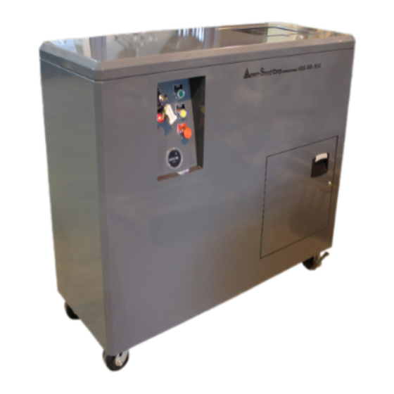
SHREDDER OPERATION INFEED SLOT OPTIONAL OUTPUT CONVEYOR CONTROL PANEL Key Switch Power Light Forward Reverse E-Stop DUAL INFEED SLOTS: HD-SSD MODELS HDD = HARD SSD = SOLID DISK DRIVES STATE DRIVES Service Department: 888.270.6879... -
Page 7: Start Up Procedure
SHREDDER DIFFERENCES - HD, SSD & HD-SSD MODELS HD models have 1.5” or 3/4” wide cutters. They can shred solid state drives, but not to a secure particle size. SSD models have 3/8” wide cutters. They cannot shred hard disc drives, which require much wider cutters. HD-SSD models use two separate cutter heads to allow you to destroy both magnetic hard drives as well as electronic media in the same shredder. -
Page 8: Server Drive Jam Warning
SERVER DRIVE JAM WARNING MATERIAL TESTED: 1” Hard Drives: One per feed approximately every 20 seconds Notebook Drive: Three per feed approximately every 20 seconds DLT Tapes: One per feed approximately every 20 seconds WARNING - UNLIKE SOLID STATE, SOME ROTATIONAL HARD DRIVES ARE CONSTRUCTED IN A WAY THAT MAY WARRANT EXTRA ATTENTION. -
Page 9: Clearing A Jam
CLEARING A JAM Should a jam occur, the machine will turn itself off. Ensure that all personnel are clear of both the input chute and the cutter head. Momentarily depress the yellow REVERSE pushbutton. This will cause the cutters to run backwards for as long as the REVERSE pushbutton remains depressed. -
Page 10: Troubleshooting
TROUBLE SHOOTING “WARNING” LOCK OUT POWER before performing any cleaning, oiling, maintenance, or trouble shooting. PROBLEM POSSIBLE CAUSE REMEDY Defective STOP button. Check continuity (N.C.) If bad, replace. Check each leg of forward side of Machine will not turn off using STOP contactor for continuity. -
Page 11: Maintenance
MAINTENANCE - CLEANING ALWAYS lock off power first. Daily cleaning (After 8 hours of operation) Remove debris that has built up on the cutters and combers using compressed air (maximum 40 psi) or vacuum. Use heavy gloves to remove magnetic material from cutter-head. ... - Page 12 LUBE SCHEDULE ITEM LUBE FREQUENCY TYPE LUBE Spur gears Weekly Open Gear Lube (Aerosol) Check weekly Gear Oil: High Grade, Petroleum Reducer Based, Rust & Oxidation Inhibited Drain and refill yearly (2500 hours) Cutters Every 4 to 8 hours 10W, 20W, 30W Motor Oil Output conveyor pulley bearings Monthly Multipurpose Grease...
- Page 13 MAINTENANCE CHECKLIST - DAILY Service Department: 888.270.6879...
-
Page 14: Maintenance Checklists
MAINTENANCE CHECKLIST - WEEKLY Service Department: 888.270.6879... - Page 15 MAINTENANCE CHECKLIST - MONTHLY Service Department: 888.270.6879...
- Page 16 MAINTENANCE CHECKLIST - YEARLY Service Department: 888.270.6879...
-
Page 17: Conveyor Belt Adjustment
CONVEYOR BELT ADJUSTMENT ALIGNMENT AND TENSIONING Read all safety warnings (see page 5) before proceeding. Lock power off. Mark the initial position. By design, the conveyor belt should have 1/16” or less clearance to side frames. This assists in preventing debris from getting under the belt but some side rubbing may be expected. -
Page 18: Cutter Assembly - Hd-Ssd Models
HD-SSD MODELS CUTTER HEAD ASSEMBLY - 3/8” & 1-1/2” SHRED WIDTH ITEM QTY PART # DESCRIPTION ITEM QTY PART # DESCRIPTION GEAR BOX: CONSULT FACTORY 34575 SSD TIE BAR SPACERS 111907 BEARING 33616 DRIVE SHAFT CUTTER 34592 WEAR BLOCK 33617 IDLE SHAFT CUTTER 34591 WEAR BLOCK 33584 DRIVE BEARING BLOCK 34590 SSD OUTSIDE COMBER... - Page 19 HD-SSD MODELS CUTTER HEAD ASSEMBLY - 3/8” & 3/4” SHRED WIDTH ITEM QTY PART # DESCRIPTION ITEM QTY PART # DESCRIPTION GEAR BOX: CONSULT FACTORY 33584 DRIVER BEARING BLOCK 111907 BEARING 33585 IDLE BEARING BLOCK 34592 WEAR BLOCK 34267 SSD CUTTER STYLE 1 34886 WEAR BLOCK 34268 SSD CUTTER STYLE 2 34590 SSD OUTSIDE COMBER...
-
Page 20: Cutter Assembly - Hd Models
HD MODELS CUTTER HEAD ASSEMBLY - 1-1/2” SHRED WIDTH ITEM PART # DESCRIPTION ITEM PART # DESCRIPTION 33584 DRIVE BEARING BLOCK 33587 SPACER 33585 IDLE BEARING BLOCK 33663 SPACER REDUCER: CONSULT FACTORY 33772 SIDE PLATE 33615 DRIVE SHAFT 33772 SIDE PLATE 33616 DRIVE SHAFT CUTTER 33625... - Page 21 HD MODELS CUTTER HEAD ASSEMBLY - 3/4” SHRED WIDTH ITEM PART # DESCRIPTION ITEM PART # DESCRIPTION 33584 DRIVE BEARING BLOCK 33620-.75 COMBER TIE BARS 33585 IDLE BEARING BLOCK 33619-.75 WEAR BLOCK REDUCER: CONSULT FACTORY 33617-.75 IDLE SHAFT CUTTER 33615 DRIVE SHAFT 33616-.75 DRIVE SHAFT CUTTER...
-
Page 22: Cutter Assembly - Ssd Models
SSD MODELS CUTTER HEAD ASSEMBLY - 3/8” SHRED WIDTH ITEM PART # DESCRIPTION ITEM PART # DESCRIPTION 33584 DRIVE BEARING BLOCK SPUR GEAR 33585 IDLE BEARING BLOCK 34267 CUTTER STYLE 1 REDUCER: CONSULT FACTORY 34268 CUTTER STYLE 2 33615 DRIVE SHAFT 34269 CUTTER STYLE 3 33618... -
Page 23: Output Conveyor
OUTPUT CONVEYOR (OPTIONAL) ITEM QTY PART # DESCRIPTION ITEM QTY PART # DESCRIPTION 34857 OPP CONVEYOR SIDE FRAME OPP 33893 OPP BEARING MOUNT ANGLE 34857 CONVEYOR SIDE FRAME 33893 BEARING MOUNT ANGLE 34858 CONVEYOR LEG 33975 DRIVE SHAFT GUARD 34859 CROSSMEMBER 33911 END GUARD UHMW COVER... -
Page 24: Electrical Diagrams - 1.5 Hp Models
ELECTRICAL DIAGRAM - 1.5 HP MODELS, 120V - 1 PHASE Service Department: 888.270.6879... - Page 25 ELECTRICAL DIAGRAM - 1.5 HP MODELS, 220V - 1 PHASE Service Department: 888.270.6879...
- Page 26 ELECTRICAL DIAGRAM - 1.5 HP MODELS, 208V - 3 PHASE Service Department: 888.270.6879...
- Page 27 ELECTRICAL DIAGRAM - 1.5 HP MODELS, 230V - 3 PHASE Service Department: 888.270.6879...
- Page 28 ELECTRICAL DIAGRAM - 1.5 HP MODELS, 460V - 3 PHASE ITEM PART # DESCRIPTION 112054 CORD CONNECTOR - 460V/3PH FU-3 111200 FUSE 2 AMP TIME DELAY 111403 OVERLOAD - CONVEYOR - .40-.63 AMP 111281 MOTOR STARTER - CONVEYOR - 9 AMP 104778 SO CORD 104768...
- Page 29 ELECTRICAL DIAGRAM - 1.5 HP MODELS, 575V - 3 PHASE Service Department: 888.270.6879...
-
Page 30: Electrical Diagrams - 3 Hp Models
ELECTRICAL DIAGRAM - 3 HP MODELS, 208V - 3 PHASE Service Department: 888.270.6879... - Page 31 ELECTRICAL DIAGRAM - 3 HP MODELS, 230V - 3 PHASE Service Department: 888.270.6879...
- Page 32 ELECTRICAL DIAGRAM - 3 HP MODELS, 460V - 3 PHASE Service Department: 888.270.6879...
- Page 33 ELECTRICAL DIAGRAM - 3 HP MODELS, 575V - 3 PHASE Service Department: 888.270.6879...
- Page 34 3490 US 23 N Alpena, MI 49707 Toll Free: 800-634-8981 Phone: 989-358-6121 Fax: 989-358-6122 info@ameri-shred.com www.ameri-shred.com Service Department: 888.270.6879...
Need help?
Do you have a question about the AMS-150HD and is the answer not in the manual?
Questions and answers