Table of Contents
Advertisement
Quick Links
R-410A
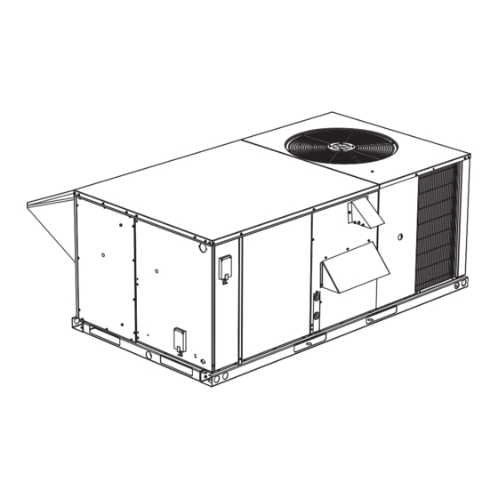
DM SERIES
3 - 6.3 Ton
50 Hertz
General . . . . . . . . . . . . . . . . . . . . . . . . . . . . . . . . . . . . . . . . . . 3
Installation . . . . . . . . . . . . . . . . . . . . . . . . . . . . . . . . . . . . . . . . 7
Installation Safety Information. . . . . . . . . . . . . . . . . . . . . . . 7
Limitations . . . . . . . . . . . . . . . . . . . . . . . . . . . . . . . . . . . . . . 7
Location. . . . . . . . . . . . . . . . . . . . . . . . . . . . . . . . . . . . . . . . 8
Rigging And Handling . . . . . . . . . . . . . . . . . . . . . . . . . . . . . 8
Condensate Drain . . . . . . . . . . . . . . . . . . . . . . . . . . . . . . . . 9
Compressors. . . . . . . . . . . . . . . . . . . . . . . . . . . . . . . . . . . . 9
Filters . . . . . . . . . . . . . . . . . . . . . . . . . . . . . . . . . . . . . . . . . 9
Service Access . . . . . . . . . . . . . . . . . . . . . . . . . . . . . . . . . . 9
DM036-072) . . . . . . . . . . . . . . . . . . . . . . . . . . . . . . . . . . . 12
Thermostat . . . . . . . . . . . . . . . . . . . . . . . . . . . . . . . . . . . . 12
Power And Control Wiring. . . . . . . . . . . . . . . . . . . . . . . . . 12
Optional Electric Heat . . . . . . . . . . . . . . . . . . . . . . . . . . . . 13
Optional Gas Heat. . . . . . . . . . . . . . . . . . . . . . . . . . . . . . . 14
Gas Piping. . . . . . . . . . . . . . . . . . . . . . . . . . . . . . . . . . . . . 14
Gas Connection . . . . . . . . . . . . . . . . . . . . . . . . . . . . . . . . 15
L.p. Units, Tanks And Piping. . . . . . . . . . . . . . . . . . . . . . . 15
Vent And Combustion Air Hoods . . . . . . . . . . . . . . . . . . . 16
Jade Economizer Interface Overview . . . . . . . . . . . . . . . . 17
Simplicity SE Economizer Sequences . . . . . . . . . . . . . . . 19
Dry Bulb Changeover . . . . . . . . . . . . . . . . . . . . . . . . . . . . 19
Single Enthalpy Changeover. . . . . . . . . . . . . . . . . . . . . . . 19
Dual Enthalpy Changeover . . . . . . . . . . . . . . . . . . . . . . . . 19
Auto. . . . . . . . . . . . . . . . . . . . . . . . . . . . . . . . . . . . . . . . . . 19
Free Cooling Operation. . . . . . . . . . . . . . . . . . . . . . . . . . . 19
Power Exhaust . . . . . . . . . . . . . . . . . . . . . . . . . . . . . . . . . 20
Operation . . . . . . . . . . . . . . . . . . . . . . . . . . . . . . . . . . . . . 20
DM036-076 Unit Weights . . . . . . . . . . . . . . . . . . . . . . . . . 25
Phasing . . . . . . . . . . . . . . . . . . . . . . . . . . . . . . . . . . . . . . . 34
Supply Air Blowers . . . . . . . . . . . . . . . . . . . . . . . . . . . . . . 35
Checking Supply Airflow Rate. . . . . . . . . . . . . . . . . . . . . . 35
Operation . . . . . . . . . . . . . . . . . . . . . . . . . . . . . . . . . . . . . . . 36
Cooling Sequence Of Operation . . . . . . . . . . . . . . . . . . . . 36
Electric Heating Sequence Of Operations . . . . . . . . . . . . 38
TABLE OF CONTENTS
Safety Controls . . . . . . . . . . . . . . . . . . . . . . . . . . . . . . . . . 38
Heat Anticipator Setpoints. . . . . . . . . . . . . . . . . . . . . . . . . 39
Gas Heating Sequence Of Operation . . . . . . . . . . . . . . . . 39
Gas Heat Operation Errors . . . . . . . . . . . . . . . . . . . . . . . . 39
Flash Codes Or Error Messages. . . . . . . . . . . . . . . . . . . . 40
Heat Anticipator Setpoints. . . . . . . . . . . . . . . . . . . . . . . . . 40
Start-up (Cooling) . . . . . . . . . . . . . . . . . . . . . . . . . . . . . . . . . 41
Prestart Check List . . . . . . . . . . . . . . . . . . . . . . . . . . . . . . 41
Operating Instructions . . . . . . . . . . . . . . . . . . . . . . . . . . . . 41
Post Start Check List. . . . . . . . . . . . . . . . . . . . . . . . . . . . . 41
Shut Down. . . . . . . . . . . . . . . . . . . . . . . . . . . . . . . . . . . . . 41
Start-up (Gas Heat) . . . . . . . . . . . . . . . . . . . . . . . . . . . . . . . . 41
Pre-start Check List. . . . . . . . . . . . . . . . . . . . . . . . . . . . . . 41
Operating Instructions . . . . . . . . . . . . . . . . . . . . . . . . . . . . 41
Post-start Check List (Gas) . . . . . . . . . . . . . . . . . . . . . . . . 41
Manifold Gas Pressure Adjustment. . . . . . . . . . . . . . . . . . 42
Pilot Checkout . . . . . . . . . . . . . . . . . . . . . . . . . . . . . . . . . . 42
Burner Instructions . . . . . . . . . . . . . . . . . . . . . . . . . . . . . . 42
Burner Air Shutter Adjustment . . . . . . . . . . . . . . . . . . . . . 42
Checking Gas Input. . . . . . . . . . . . . . . . . . . . . . . . . . . . . . 42
Adjustment Of Temperature Rise . . . . . . . . . . . . . . . . . . . 43
Troubleshooting . . . . . . . . . . . . . . . . . . . . . . . . . . . . . . . . . . 44
Cooling Troubleshooting Guide. . . . . . . . . . . . . . . . . . . . . 44
Gas Heat Troubleshooting Guide . . . . . . . . . . . . . . . . . . . 45
Flash Code Troubleshooting . . . . . . . . . . . . . . . . . . . . . . . 46
Symptomatic Troubleshooting. . . . . . . . . . . . . . . . . . . . . . 48
Unit Flash Codes. . . . . . . . . . . . . . . . . . . . . . . . . . . . . . . . 49
Fan On And Off Delays . . . . . . . . . . . . . . . . . . . . . . . . . . . 49
Simplicity SE Control Board Navigation Components . . . . . . 50
Basic Unit Control Board Navigation Examples: . . . . . . . . 51
Typical Wiring Diagrams . . . . . . . . . . . . . . . . . . . . . . . . . . . . 59
Simplicity® Lite Control Board . . . . . . . . . . . . . . . . . . . . . 59
Simplicity® Smart Equipment (SSE) . . . . . . . . . . . . . . . . . 63
Start-Up Sheet . . . . . . . . . . . . . . . . . . . . . . . . . . . . . . . . . . . 67
A
Advertisement
Table of Contents
Troubleshooting

Related Manuals for York DM SERIES


Summarization of Contents
General Unit Information
Safety Considerations
Alert symbol for potential personal injury; understand DANGER, WARNING, CAUTION.
Installation Procedures
Installation Safety Information
Read instructions before installation; ensure consumer has them for reference.
Unit Limitations and Location
Limitations
Units must be installed in accordance with applicable codes and standards.
Location
Guidelines for selecting a suitable outdoor installation location.
Rigging and Handling
Rigging And Handling
Exercise care when moving unit; use lifting holes and spreader bars.
Clearances and Drain
Clearances
Maintain adequate combustion and ventilation air per codes; refer to Table 17 for specific clearances.
Condensate Drain
Plumbing must conform to local codes; use a sealing compound on threads; trap the drain line.
Component Details
Compressors
Units shipped with factory-adjusted mountings; remove shipping brackets.
Filters
Filters must be installed ahead of evaporator coil and kept clean or replaced.
Service Access
Removable panels provide access to serviceable components.
Wiring Diagrams
Typical Power Wiring
Diagram showing field-supplied disconnect and power supply connections.
Typical Control Wiring
Diagram showing thermostat and control terminal block connections.
Thermostat and Electrical Wiring
Thermostat Installation
Location and wire requirements for installing the room thermostat.
Power And Control Wiring
Field wiring must conform to NEC/CEC codes; ensure electrical grounding.
Optional Heating
Optional Electric Heat
Factory-installed heaters wired for single point power supply; elements extend into supply air chamber.
Optional Gas Heat
Gas-fired heaters use aluminized/stainless steel heat exchangers with spark ignition.
Gas Piping and Connection
Gas Piping
Sizing depends on gas flow, gravity, and run length; follow national/local codes.
Gas Connection
Routing gas supply line through knockouts or base openings; use grommets.
L.P. Gas Considerations
Units shipped for natural gas, convertible to L.P. gas with kit; conform to NFPA standards.
Ventilation Hoods
Vent And Combustion Air Hoods
Hoods shipped attached; must be installed to assure proper unit function.
Optional Economizer/Motorized Damper Rain Hood
Instructions for field assembly of economizer rain hood onto a unit.
Economizer Setup and Interface
Economizer Set Point Adjustments
Setting economizer minimum position during occupied mode for optimal performance.
Economizer Interface Overview
Consists of LCD display and 4-button keypad for navigation and settings.
Simplicity SE Economizer Features
Free Cooling Options
Four types available: dry bulb, single enthalpy, dual enthalpy, and Auto.
Economizer Operation Modes
Economizer With Dual Enthalpy Sensors
Uses second sensor in return air for efficiency; chooses lowest enthalpy.
Economizer With Power Exhaust
Power exhaust motor energizes 45 sec after actuator position exceeds set point.
Motorized Outdoor Air Dampers
Damper drives open to set position; spring returns fully closed when circuit opens.
Cooling Sequence of Operation
Cooling Sequence Of Operation
Describes how the unit operates during cooling calls, including economizer use.
Continuous Blower
How to set the thermostat for continuous blower operation.
Intermittent Blower
How the blower operates with thermostat in AUTO mode.
No Outdoor Air Options
Cooling sequence when no economizer or outdoor air options are present.
Cooling Operation Errors
High-Pressure Limit Switch
If switch opens, compressor de-energized, ASCD initiated, condenser fan stops.
Low-Pressure Limit Switch
If switch fails to close or opens for >5s, compressor de-energized, ASCD initiated.
Freezestat (Simplicity Lite Control)
If opens, compressor de-energized, ASCD initiated, condenser fan stops.
Evaporator Low Limit (Simplicity SE Control)
If sensor detects temp below 26°F, compressor de-energized, ASCD initiated.
Low Ambient Cooling
Operates compressors in 10 min on, 5 min off cycle for defrost.
System Safety Controls
Safety Controls
Monitors suction line freezestat, high-pressure switch, low-pressure switch, and temperature limits.
Compressor Protection
Includes inherent protection, Anti-Short Cycle Delay (ASCD), and minimum run time.
Gas Heating Operation
Gas Heating Sequence Of Operation
Step-by-step process for gas heating operation, including ignition and blower.
Gas Heat Operation Errors
ICB monitors safety devices; fault state causes immediate gas valve closure.
Heat Anticipator Setpoints
Importance of correct anticipator setting for heat cycle length and temperature swing.
Gas Heating Limits and Valves
Temperature Limits
Primary and auxiliary limits protect against excessive heat exchanger tube temperatures.
Gas Valve and Centrifugal Switch
UCB monitors gas valve operation; redundant valve ensures safety.
Start-Up Procedures
Start-Up (Cooling)
Prestart checklist, operating instructions, post-start checks, and shutdown for cooling.
Start-Up (Gas Heat)
Pre-start checklist, operating instructions, and post-start checks for gas heating.
Gas System Checks
Manifold Gas Pressure Adjustment
Adjusting pressure regulator screw on automatic gas valve for high-fire gas flow.
Burner Instructions
Procedures for checking or changing burners, pilot, or orifices.
Burner Air Shutter Adjustment
Adjust shutters to avoid yellow flame in heat exchanger tubes.
Natural Gas Input Check
Steps to check gas input using a gas meter for natural gas.
Gas Rate and Temperature Rise
Table 27: Gas Rate - Cubic Feet Per Hour
Table correlating gas meter seconds per revolution to cubic feet per hour.
Adjustment Of Temperature Rise
Ensuring temperature rise is within rating plate and Gas Heat Application Table ranges.
Troubleshooting - Cooling System
Cooling Troubleshooting Guide
Steps to diagnose cooling system issues, focusing on blower and compressor operation.
System Troubleshooting Guides
Cooling Troubleshooting Guide (Continued)
Diagnosing issues related to thermostat signals, economizer, protective switches, and UCB faults.
Gas Heat Troubleshooting Guide
Safety precautions and initial steps for troubleshooting gas heat components.
Ignition Control and Centrifugal Switch Issues
Ignition Control Board Troubleshooting
Diagnosing issues related to the ignition control board and its flash codes.
Centrifugal Switch Troubleshooting
Troubleshooting faults indicated by the centrifugal switch.
Furnace Safety Switch Troubleshooting
Rollout Switch
Common causes for rollout switch opening and troubleshooting steps.
Flame Sense Circuit
Troubleshooting pilot flame and sensor issues.
Symptomatic Troubleshooting
Symptomatic Troubleshooting
Diagnosing blower or draft motor issues when furnace is not operating correctly.
Unit Fault Codes and Fan Delays
Unit Flash Codes
Explanation of flash codes used by UCB and ICB for troubleshooting.
Fan On And Off Delays
How to field adjust fan ON/OFF delays for gas and electric heat options.
Simplicity SE Control Board Navigation
Simplicity SE Control Board Navigation Components
Identifies components needed to access Simplicity SE control points and where to find guides.
Simplicity SE Navigation Examples
Understanding the Local LCD
Demonstrates navigating the LCD display from start-up to status menus.
Simplicity SE Navigation Examples (Continued)
Commissioning Menu Navigation
Demonstrates navigating the commissioning menu to view and change parameters.
Simplicity SE UCB Details
Table 30: Simplicity SE UCB Details
Details of thermostat connection strip and limit/shutdown connections on the UCB.
UCB Terminal Details
Terminal Thermostat Connection Strip
Details of thermostat connection terminals (W1, W2, Y1, Y2, G, OCC, R, X, SD-24, C) on the UCB.
UCB LEDs
Description of POWER, FAULT, and SA BUS LEDs on the UCB.
Space Temperature Sensor Connections
Details of ST, COM, SSO connections for space temperature sensors.
UCB Pin Connections
Pin Temperature Sensor Connections
Details of temperature sensor connections (SAT, RAT, OAT, ECI, CC1, CC2, EC2).
Pinned Connections on Right Edge of UCB
Details of RAH+, DCT PRS+, DFS, APS, C, VFD connections.
UCB Output and Input Details
Table 30: Simplicity SE UCB Details (Continued)
Details of HPS, LPS, FAN OVR, PWR, C, VFDFLT connections.
24V For Outputs
Details of 24V hot outputs for various components like H1, H2, C1, C2.
UCB Communication and Interface
Terminal SA BUS Connections
Details of SA BUS connections for communication with other devices.
Item Integrated User Interface
Description of the display, ENTER, CANCEL, and JOY buttons.
UCB USB and Communication Sub-board
Item USB Connector
Details of the USB connector for board parameter backup and software updates.
Optional Communication Sub-board
Details of FC BUS connections and LEDs on the communication sub-board.
Simplicity Lite Wiring Diagrams
Figure 26: Typical DM036, 048 With Simplicity Lite Control, With/without Electric Heat Wiring Diagram
Wiring diagram for DM036/048 units with Simplicity Lite control and electric heat.
Simplicity Lite Wiring Diagrams (Gas Heat)
Figure 27: Typical DM036, 048 With Simplicity Lite Control, With Gas Heat Wiring Diagram
Wiring diagram for DM036/048 units with Simplicity Lite control and gas heat.
Simplicity Lite Wiring Diagrams (Electric Heat)
Figure 28: Typical DM060, 076 With Simplicity Lite Control, With/Without Electric Heat Wiring Diagram
Wiring diagram for DM060/076 units with Simplicity Lite control and electric heat.
Simplicity Lite Wiring Diagrams (Gas Heat)
Figure 29: Typical DM060, 076 With Simplicity Lite Control, With Gas Heat Wiring Diagram
Wiring diagram for DM060/076 units with Simplicity Lite control and gas heat.
Simplicity SE Wiring Diagrams (Electric Heat)
Figure 30: Typical DM036, 048 With Simplicity SE Control, With/without Electric Heat Wiring Diagram
Wiring diagram for DM036/048 units with Simplicity SE control and electric heat.
Simplicity SE Wiring Diagrams (Gas Heat)
Figure 31: Typical DM036, 048 With Simplicity SE Control, With Gas Heat Wiring Diagram
Wiring diagram for DM036/048 units with Simplicity SE control and gas heat.
Simplicity SE Wiring Diagrams (Electric Heat)
Figure 32: Typical DM060, 076 With Simplicity SE Control, With/without Electric Heat Wiring Diagram
Wiring diagram for DM060/076 units with Simplicity SE control and electric heat.
Simplicity SE Wiring Diagrams (Gas Heat)
Figure 33: Typical DM060, 076 With Simplicity SE Control, With Gas Heat Wiring Diagram
Wiring diagram for DM060/076 units with Simplicity SE control and gas heat.
Start-Up Documentation
START-UP & SERVICE DATA INSTRUCTION
Checklist for commercial package units, covering installation and startup procedures.
WARRANTY STATEMENT
Details of the warranty policy for equipment start-up failures.
EQUIPMENT STARTUP
Guidance on using local LCD or Mobile Access Portal for startup.
Safety and Application Information
SAFETY WARNINGS
General industry knowledge and experience required for technician safety.
DESIGN APPLICATION INFORMATION
Information from specifying engineer on airflow and static pressure requirements.
Reference Checklists
General Inspection Checklist
Checklist for general unit inspections before and after installation.
Air Moving Inspection Checklist
Checks for drive component alignment, belt tension, and pulley tightness.
Exhaust Inspection Checklist
Checks for hub tightness, fan blade clearance, rotation, and mounting.
Economizer Inspection Checklist
Checks for CO2 sensor, economizer settings, and operation.
Operating Measurements
Air Flow Measurements
Procedures and data recording for measuring fan operation, airflow, and motor data.
Electrical Data Recording
Table for recording measured amperage for various unit components.
Cooling Measurements and Safeties
Cooling Operating Measurements
Table for recording refrigerant pressures, temperatures, and superheat.
Refrigerant Safeties Checks
Checks for compressor rotation, high/low pressure safety verification.
Gas Heating Measurements
Gas Heating Operating Measurements
Checks for gas leaks, vent motor, safety operations, and manifold pressure.
Staging Controls and Final Inspection
Staging Controls Verification
Verifying proper operation of heating/cooling staging controls via thermostat or BAS.
Variable Frequency Drive Verification
Verifying VFD operation and motor speed modulation with duct pressure.
Final Inspection Checklist
Verifying setpoints, option parameters, and secured access panels.
Observed Product Deficiencies & Concerns
Space for recording any observed product deficiencies or concerns.
Need help?
Do you have a question about the DM SERIES and is the answer not in the manual?
Questions and answers