Table of Contents
Advertisement
Advertisement
Table of Contents

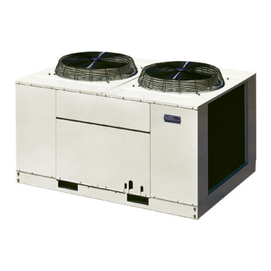
Summary of Contents for Carrier 38AE Series
- Page 1 Installation Manual...
-
Page 2: Table Of Contents
CONTENTS PAGE SAFETY CONSIDERATIONS Safety considerations…………………… Installation……...……………………...….. Installing, starting up, and Step 1 – complete pre-installation checks.. servicing air-conditioning Step 2 – rig and mount the unit…………… equipment can be Step 3 – complete electrical connections.. hazardous due to system Pre-start-up………………………...………. - Page 4 Description Air Cooled Condensing Unit Description Air Cooled Condensing Unit Product Model 38AE020 38AE025 38AE030 38AE040 38AE050 38AE060 58,900 82,300 94,000 118,100 160,600 177,200 Model 38AE010 38AE015 38AE020 38AE025 38AE030 38AE040 38AE050 38AE060 Nominal Cooling Capacity Btu/hr. 201,000 281,000 321,000 403,000 548,000 604,900...
- Page 5 Description Air Cooled Condensing Unit Product Model 38AF020 38AF025 38AF030 38AF040 38AF050 38AF060 58,000 82,000 93,000 117,000 161,000 180,000 Nominal Cooling Capacity Btu/hr. 200,000 280,000 320,000 400,000 550,000 615,000 Power Supply Amp. Type Semi-Hermetic Reciprocating y t i Compressor . l a 2…..2.4 2…..2.4 Type...
- Page 6 Dimension 38AE020-040 / 38AF020-040 38AE050-060 / 38AF050-060...
-
Page 7: Step 2 - Rig And Mount The Unit
Step 2 – Rig and mount the Unit COMPRESSOR MOUNTING –As shipped, the compressor is held tightly in place by self- locking bolts. Be sure unit panels are securely in place prior to rigging. Before starting unit, loosen self-locking RIGGING – These units are designed for bolts until the snubbed washer can be overhead rigging only. -
Page 8: Step 3 - Complete Electrical Connections
INSTALL LIQUID LINE SOLENOID VALVE — INSTALLLIQUID LINE SOLENOIDVALVE SOLENOID DROP—It is recommended that a (OPTIONAL) CAPACITY CONTROLS — If 2- solenoid valve be placed in the main liquid line step cooling is desired, place a solenoid valve (see Fig. 4) between condensing unit (38AE) in the location shown in Fig. -
Page 9: Pre-Start-Up
PRE-START-UP Evacuate and Dehydrate the entire refrigerant system by either of the methods described in Carrier Standard Service Techniques Manual, Chapter 1. Leak Test the entire refrigerant system by the pressure method described in Carrier Standard Service Techniques Manual, Chapter l. Use R-22 at approximately 25 psig (172.4 kPa) backed up with an inert gas to a total pressure not to exceed 245 psig (1689 kPa). -
Page 10: Service
SERVICE Capacity Control –A suction pressure-actuated unloader controls 2 cylinders and provides capacity control. Unloaders are factory set (see Tables l.), but can be field adjusted as described in the 2 following sections. Time Guard ll Circuit – Prevents short – cycling by providing a delay of approximately 5 minutes before restarting compressor after shutdown from safety device action. -
Page 11: Lubrication
Lubrication FAN MOTORS have sealed bearings. No provisions are made for lubrication. COMPRESSOR has its own oil supply. Loss of oil due to a leak in the system should be the only reason for adding oil after the system has been in operation. See oil Charge section. Cleaning Coils –The coils can be cleaned with a vacuum cleaner, washed out with Turn off unit power. - Page 12 TROUBLESHOOTING PROBLEM Problem Solution COMPRESSOR DOES NOT RUN Contractor Open Restore power. Power off. After finding cause and correcting. Replace with Fuses blown in field power circuit. correct size fuse. Check secondary fuse(s); replace with correct type No control power. and size.
-
Page 13: Troubleshooting
TROUBLESHOOTING (cont.) Problem Solution COMPRESSOR CYCLES ON LOW- PRESSURE SWITCH (cont.) Airflow Restricted Check refrigerant charge. Coil iced up. Clean coil fins. Coil dirty. Clean or replace filters. Air filters dirty. Check damper operation and position. Dampers closed. Indoor-Air Fan Stopped Tighten all connections. -
Page 14: Wiring Diagram
Wiring Diagram 38AE020 / 38AF020... - Page 15 Wiring Diagram 38AE025, 030, 040 / 38AF025, 030, 040...
- Page 16 Wiring Diagram 38AE050, 060 / 38AF050,060...
- Page 17 Control Module (CM) Operation When voltage is applied the power LED (DSI) will continuously flash 1/4 second off. The module starts a 3-minute compressor delay timer. This delay can be bypassed by pressing the override switch for at least 1/2 second. The Status LED (DS3) must be flashing or the override switch will not function.
-
Page 18: Start-Up Checklist
TART-UP CHECKLIST A. Preliminary Information Outdoor: model no._______________________ Serial no.___________ Indoor: air handler manufacturer____________________________ Model no._____________________________ Serial no.__________ Additional accessories_________________________________________ B. Pre-Start-Up Outdoor Unit Is there any shipping damage? ____________ (y/n)_________________ If so, where: ______________________________________________________ Will this damage prevent unit start-up? (y/n)________________ Check power suppy.


Need help?
Do you have a question about the 38AE Series and is the answer not in the manual?
Questions and answers