
Related Manuals for WABCO ESC


Summarization of Contents
Service Notes
About This Manual
Contains maintenance procedures for WABCO ABS, RSC, ESC, and HSA systems.
Before You Begin
Instructions and procedures to follow before starting component service.
Hazard Alert Messages and Torque Symbols
Explains warning symbols and hazard alert messages for safety.
Obtaining Additional Information
Provides contact information for obtaining further WABCO product details.
Asbestos and Non-Asbestos Fibers
Hazard Summary
Summarizes potential hazards of asbestos and non-asbestos fiber exposure.
Recommended Work Practices
Outlines procedures to reduce exposure to brake dust during servicing.
Regulatory Guidance
References US regulatory agencies for guidance on safety procedures.
1 Introduction
Anti-Lock Braking System (ABS)
Explains the purpose and function of the ABS system in maintaining traction.
System Components
Overview of key components within the ABS, RSC, and ESC systems.
Electronic Control Unit (ECU)
Describes the ECU as the control center for ABS, RSC, and ESC systems.
Wheel Speed Sensing Systems
Explains wheel speed sensors and their function in providing wheel speed data.
Pressure Modulator Valves
Explains modulator valves control air pressure for ABS, RSC, or ESC events.
Active Braking Valves (ABV)
Describes ABVs as solenoid valves used for active braking during ATC, RSC, or ESC.
Brake Pressure Sensor (BPS)
Explains the BPS provides brake demand information to the system.
Steering Angle Sensor (SAS)
Describes the SAS as part of the ESC system, providing steering input to the ECU.
Off-Road ABS Switch
Explains the off-road ABS switch function for improved vehicle control.
ATC Switch
Details the ATC switch functionality and configuration settings.
Blink Code Switch
Explains the Blink Code switch for simple troubleshooting information.
System Configuration
Defines system configuration by wheel speed sensors and modulator valves.
2 Stability and Safety Enhancement Systems
ATC Operation
Explains Automatic Traction Control (ATC) for improving traction in low-traction conditions.
ATC Components
Lists ATC components, including active braking valves and modulator valves.
ATC Switch
Details the ATC switch functionality and configuration settings.
Roll Stability Control (RSC)
Explains RSC assists drivers in managing rollover conditions by adjusting engine and brakes.
RSC Components
Lists RSC components, including ABS parts and an internal accelerometer.
Electronic Stability Control (ESC)
Describes ESC combining rollover and directional stability for spinout/drift control.
ESC Components
Lists ESC components, including ABS, ATC, RSC parts, ABVs, pressure sensor, ESC module, SAS.
Hill Start Aid (HSA)
Explains HSA supports automated manual transmissions to prevent rollback on grades.
HSA Components
Lists HSA components, built on ABS ECUs with E4.4 software or higher.
Drag Torque Control
Explains drag torque control uses ABS ECU to increase engine RPM to prevent drive axle lock-up.
Lift Axle Capability
Describes lift axle capability for six-sensor ABS ECUs with ATC.
3 Diagnostics, Troubleshooting and Testing
General Maintenance Information
States no scheduled maintenance is required for ABS, ATC, RSC, ESC systems.
Lamp Check and ABS Wheel Speed Sensors
Details checking ABS lamps, wheel speed sensor adjustment, and lubrication.
ABS Indicator Lamp
Explains ABS indicator lamps for status indication and blink code diagnostics.
Diagnostics
Overview of diagnostic methods including TOOLBOX™ Software.
Adapter Selection
Explains how to select the correct adapter and communication protocol in TOOLBOX.
Fault Information Display
Describes fault information display including SPN, SID, FMI, and repair instructions.
Blink Code Diagnostics
Explains how to use blink codes for ABS fault diagnostics.
Definitions
Defines terms related to blink codes like ABS Indicator Lamp, Blink Code, etc.
Clear Mode
Explains how to enter and use Clear Mode to erase faults from the ECU.
Blink Code Illustrations
Illustrates blink code patterns for active faults, stored faults, and system OK.
Blink Code Conditions and Identification
Lists conditions for blink codes and provides tables for code identification.
Wheel Speed Sensor Testing
Details sensor adjustment and electrical checks for wheel speed sensors.
Modulator Valve Testing
Details electrical checks for modulator valves, including resistance and continuity.
Modulator Valve Testing with TOOLBOX™ Software
Explains how to use TOOLBOX software to cycle ABS and trailer modulator valves.
Active Braking Valves (ABV) Testing
Details electrical checks for Active Braking Valves (ABV), including resistance and continuity.
ABV Testing with TOOLBOX™ Software
Explains how to cycle Active Braking Valves using TOOLBOX™ Software.
Brake Pressure Sensor Testing
Details electrical checks for brake pressure sensor, including voltage and continuity.
Brake Pressure Sensor Testing with TOOLBOX™ Software
Explains how to test the pressure sensor using TOOLBOX™ Software.
ESC CAN Network Testing
Details checks for ESC CAN network continuity, resistance, and voltage.
ESC Module Testing
Outlines electrical checks for the ESC module, including voltage, CAN signals, and resistance.
ESC Module Mounting
Emphasizes correct mounting and leveling of the ESC module for proper operation.
ESC Information via TOOLBOX™ Software
Explains how to access ESC information using TOOLBOX™ Software.
Steering Angle Sensor (SAS) Testing
Details electrical checks for the Steering Angle Sensor (SAS).
ECU Circuit Testing
Details electrical checks for ECU circuits, including battery, ignition, and ground.
J1939 Serial Communications Testing
Details checks for J1939 serial communication, including voltage and resistance.
4 Component Replacement
Hazard Alert Messages
Lists and explains all Warning and Caution hazard alert messages.
Component Removal and Installation
General procedures for removing and installing system components.
Wheel Speed Sensors
Details sensor lubricant specifications and removal/installation procedures.
Modulator Valves
Details the removal and installation procedure for modulator valves.
Active Braking Valves (ABV)
Details the removal and installation procedure for Active Braking Valves (ABV).
ABS Valve Packages
Details the removal and installation for complete ABS valve packages.
Active Braking Valve on ABS Valve Package
Details removal and installation of ABV when mounted on the ABS valve package.
Electronic Control Unit (ECU)
Details the removal and installation procedures for the ECU.
Steering Angle Sensor (SAS) — WABCO Only
Details removal and installation procedures for the WABCO Steering Angle Sensor.
Electronic Stability Control (ESC) Module
Details removal and installation procedures for the ESC module.
Brake Pressure Sensor
Details removal and installation procedures for the brake pressure sensor.
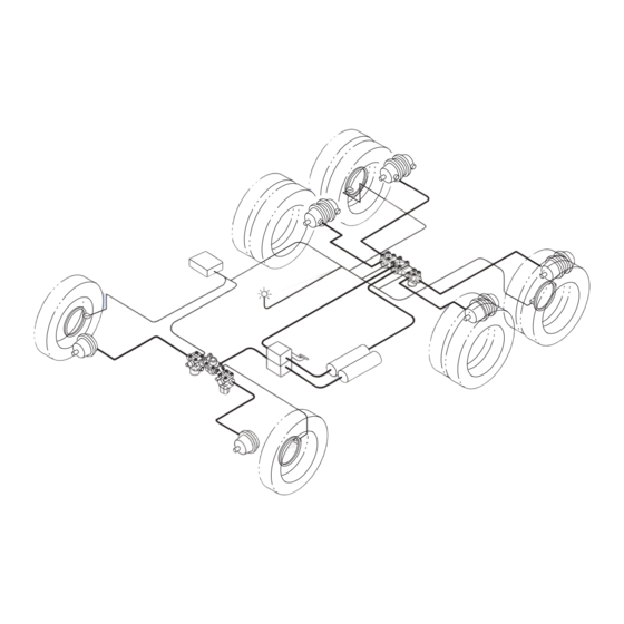
5 System Configurations
System Configuration Layouts
Shows common system configurations for ABS, ATC, RSC, ESC.
6 Wiring Diagrams and Connectors
ECU Connector Pin Assignments
Provides pin assignments for various ECU types (Basic, Universal).
Basic ECU ABS with Optional ATC (Cab-mounted)
Shows the wiring diagram for Basic ECU ABS with optional ATC (Cab-mounted).
6S/6M Universal ECU with RSC
Shows wiring for Universal ECU with RSC, including 6S/4M and 4S/4M configurations.
6S/6M Universal ECU with ESC
Shows wiring for Universal ECU with ESC, including 6S/4M and 4S/4M configurations.
6S/6M Universal ECU with ESC and HSA
Shows wiring for Universal ECU with ESC, HSA, including 6S/4M and 4S/4M.
6S/6M Frame-mounted ECU with ESC
Shows wiring for Frame-mounted ECU with ESC, including 6S/4M and 4S/4M.
4S/4M Frame-mounted ECU with SLC Feature
Shows wiring for Frame-mounted ECU with SLC feature.
6S/6M Frame-mounted ECU with ESC and HSA
Shows wiring for Frame-mounted ECU with ESC, HSA, and optional configurations.
7 SPN, SID, FMI Fault Codes
SPN, SID, FMI Diagnostic Trouble Code List
Lists SPN, SID, FMI codes with descriptions, causes, and actions.
8 Appendix I
Reconfiguration Procedure
Explains how to reconfigure ECUs, especially for E version.
How to Reconfigure an ECU (E Version)
Details the procedure for reconfiguring E version ECUs.
Manual Reconfiguration
Provides information on manual ECU reconfiguration steps.
9 Appendix II
E4 ESC End of Line Calibration Procedure
Details the E4 ESC End of Line calibration process.
SAS Calibration
Describes the SAS Calibration process, including vehicle condition and tool usage.
To access the ESC EOL
Guides on accessing the ESC End of Line menu via TOOLBOX software.
ESC Initialization
Details the ESC Initialization process following SAS calibration.
Straight Driving Adjustment
Explains the straight driving adjustment phase of ESC initialization.
Steering Ratio Calculation Tip
Advises on steering ratio calculation, including stopping and turning requirements.
10 Appendix III
E8 ESC End of Line Calibration Procedure
Details the E8 ESC End of Line calibration process using specific software versions.
SAS Calibration
Describes the SAS Calibration process for E8 ECUs using specific software.
ESC Initialization
Details the ESC Initialization process for E8 ECUs.
Straight Driving Adjustment
Explains the straight driving adjustment for E8 ESC initialization.
11 Appendix IV
Aftermarket Programming Overview
Explains aftermarket programming for pneumatic ABS ECUs.
Minimum Requirements for Aftermarket Programming
Lists minimum requirements for aftermarket programming, including software and adapters.
Aftermarket Programming Procedures
Outlines the general steps for aftermarket programming of ECUs.
Acquire Replacement ECU
Instructs to acquire a programmable ECU from Meritor Commercial Vehicle Aftermarket.
Install Replacement ECU
Instructs to install the programmable ECU into the vehicle and connect connectors.
Acquire Configuration File
Guides on acquiring a configuration file from wabco-na.snapon.com.
Load Configuration File into ECU
Explains loading the configuration file into the ECU using WABCO TOOLBOX™ software.
ECU Label Identification
Explains how to identify ECU type and required TOOLBOX™ software version.
Need help?
Do you have a question about the ESC and is the answer not in the manual?
Questions and answers