Table of Contents
Advertisement
SIMATIC HMI
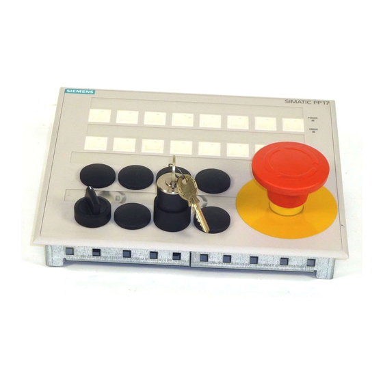
PP7, PP17-I, PP17-II
Push Button Panels
Equipment Manual
6AV3991–1CA00–0AB0
Release 06/98
www.gkbpx.com
Preface, Contents
Product Description
Starting Up the Push Button
Panel
Control Bit Assignment
Installation
Unit Description PP7
Unit Description PP17-I
Unit Description PP17-II
Attach Labeling Strips
Spare Parts
Technical Data
System Messages
Hardware Test
Siemens Worldwide
Index
该文档是极速PDF编辑器生成,
如果想去掉该提示,请访问并下载:
http://www.jisupdfeditor.com/
1
2
3
4
5
6
7
8
9
A
B
C
D
Advertisement
Table of Contents

Summarization of Contents
Preface
Purpose of the Manual
Explains the objective and scope of the equipment manual for users.
Manual Organization and Support
Details the structure of the manual and provides information on obtaining further technical support.
Product Description
Push Button Panel Applications
Describes the functionality, features, and benefits of using Siemens Push Button Panels.
Connection types and Unit Configuration
Details supported connection types and explains how the unit is configured and parameters adjusted.
Starting Up the Push Button Panel
MPI and DP Connection Setup
Details system settings and configuration for MPI and PROFIBUS-DP connections.
Configuring PLC Interface
Guides on accessing and utilizing the configuration mode for PLC interface settings.
Define Configuration in PLC
Explains PLC configuration requirements, including GSD files for various connections.
Configuring Keys and LEDs
Details parameters for configuring keys and LEDs, including pulse extension and function types.
Control Bit Assignment
Key, LED, and Input/Output Bit Mapping
Illustrates the numbering of keys, LEDs, and digital I/Os, linking them to PLC bits.
LED and Digital Output Data Areas
Shows the data areas for LEDs and digital outputs in the PLC.
Control Bits for PP7, PP17-I, PP17-II
Illustrates the data structure and control bits assigned to PP7, PP17-I, and PP17-II in the PLC.
Installation
Degree of Protection and Safety
Discusses the panel's protection rating and essential safety precautions during installation.
Mechanical Installation Procedures
Provides step-by-step instructions for the physical installation of the panel.
22.5 mm Element Installation and EMC Design
Instructions for installing 22.5 mm elements and guidelines for EMC-compatible design.
Cable, Voltage Supply, and Grounding
Information on suitable cables, safe voltage supply, and proper grounding connection.
Unit Description PP7
PP7 Dimensions and Mounting
Details the physical dimensions and required mounting cut-out for the PP7 unit.
PP7 Rear Side Connections
Identifies the components and interfaces located on the rear of the PP7 unit.
Unit Description PP17-I
PP17-I Dimensions and Mounting
Details the physical dimensions and required mounting cut-out for the PP17-I unit.
PP17-I Rear Side Connections
Identifies the components and interfaces located on the rear of the PP17-I unit.
Unit Description PP17-II
PP17-II Dimensions and Mounting
Details the physical dimensions and required mounting cut-out for the PP17-II unit.
PP17-II Rear Side Connections
Identifies the components and interfaces located on the rear of the PP17-II unit.
Attach Labeling Strips
Labeling Strip Dimensions and Text Positions
Provides dimensions and text positioning for creating custom labeling strips.
Text Positions for 22.5 mm Elements
Illustrates text placement for 22.5 mm elements on specific panel types.
Spare Parts
Memory Module and PP17-I Specific Parts
Lists available spare parts, including the memory module and items exclusive to PP17-I.
Technical Data
General Specifications and Ambient Conditions
Covers housing, voltage, environmental operating and storage conditions.
Digital Input/Output Specifications
Details electrical parameters for digital inputs and outputs.
Interface Assignment Details
Provides pinout information for communication interfaces like PROFIBUS-DP and MPI.
System Messages
Startup Messages and Error LED Signals
Explains initial system messages and interprets error LED indicators for troubleshooting.
Display Error Message Reference
A guide to understanding and resolving various error messages shown on the panel display.
Hardware Test
Activating and Using Hardware Test Mode
Instructions on how to enter and operate the hardware test mode for panel diagnostics.
Hardware Test Function List
Outlines the available functions and their purposes within the hardware test mode.
Siemens Worldwide
Siemens Sales Offices in Germany
Lists the locations of Siemens sales offices within Germany.
European Siemens Companies and Representatives
Provides a directory of Siemens entities across various European countries.
African Siemens Companies and Representatives
Lists Siemens companies and representatives located in African countries.
Siemens Companies in America
Directory of Siemens companies and representatives across North, Central, and South America.
Siemens Companies in Asia and Middle East
Lists Siemens companies and representatives in Asian countries and the Middle East.
Siemens Companies in Australia & New Zealand
Lists Siemens companies and representatives in Australia and New Zealand.


Need help?
Do you have a question about the SIMATIC PP17-I and is the answer not in the manual?
Questions and answers