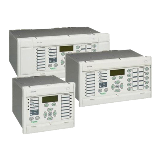
Summarization of Contents
SAFETY SECTION
STANDARD SAFETY STATEMENTS AND EXTERNAL LABEL INFORMATION FOR AREVA T&D EQUIPMENT
Provides safety statements, symbol explanations, and label information for AREVA T&D equipment, covering installation and disposal.
INTRODUCTION
Protection Features
Details various protection features like Undervoltage, Thermal overload, Overvoltage, and Power swing blocking.
Remark
Provides notes on DDB table references and version compatibility.
RELAY DESCRIPTION
RELAY SYSTEM OVERVIEW
Provides an overview of the relay's hardware modules, software architecture, and communication interfaces.
HARDWARE MODULES
Describes the key hardware components such as processor board, co-processor board, and input modules.
APPLICATION GUIDE
INTRODUCTION TO MiCOM GUIDES
Introduces the MiCOM guides, covering protection relay functions, applications, and documentation.
TECHNICAL DATA
RATINGS
Specifies current, voltage, auxiliary supply, frequency, and logic input characteristics.
ACCURACY
Details the measurement accuracy and reference conditions for various relay quantities.
ENVIRONMENTAL COMPLIANCE
Covers electrical, atmospheric, and mechanical environment specifications according to relevant standards.
INSTALLATION
RECEIPT OF RELAYS
Guidelines for inspecting relays upon receipt and handling transit damage claims.
STORAGE
Recommendations for storing relays to maintain optimal condition and prevent battery drain.
UNPACKING
Precautions to take during unpacking to avoid damaging components or losing parts.
RELAY MOUNTING
Explains rack mounting and panel mounting procedures for MiCOM relays.
COMMISSIONING
INTRODUCTION
Overview of MiCOM P440 relays, their software architecture, and commissioning principles.
SETTING FAMILIARISATION
Guides users on navigating the relay's menu and applying settings using the operator interface or PC software.
EQUIPMENT REQUIRED FOR COMMISSIONING
Lists minimum and optional equipment needed for commissioning, including test sets and software.
PRODUCT CHECKS
Details checks for relay condition, ratings, earth connection, wiring, and insulation when de-energised.
COMMISSIONING TEST RECORD
Product Checks
Details checks for relay condition, ratings, earth connection, wiring, and insulation when de-energised.
Setting Checks
Procedures for verifying application-specific settings, programmable scheme logic, and protection timing.
On-load Checks
Steps for performing checks with the relay energized, including VT and CT wiring verification.
Final Checks
Final verification steps after testing, ensuring all records are reset and the relay is ready for service.
CONNECTION DIAGRAMS
MiCOM P441 – HARDWARE DESCRIPTION
Describes the hardware components and terminal block layout of the MiCOM P441 relay.
MiCOM P441 – WIRING DIAGRAM (1/2)
Provides a wiring diagram for the MiCOM P441 relay, including opto-isolators, relays, and communication ports.
CONFIGURATION / MAPPING
Courier Data Base
Defines the menu structure, data types, and DDB elements for Courier, Modbus, and IEC60870-5-103 interfaces.
Part B: Menu datatype definition for Modbus
Details datatypes used for Modbus interface, cross-referenced to the Menu Database.
Part C: Internal digital signals (DDB)
Defines the relay's internal digital signals, including opto inputs and output contacts.
Part D: Menu Database for MODBUS
Defines the menu structure for the Modbus interface, including relay settings and measurements.
Part E: IEC60870-5-103 Interoperability Guide
Defines the operation of the IEC60870-5-103 interface, referencing communication settings.
HARDWARE / SOFTWARE VERSION HISTORY AND COMPATIBILITY
Relay type: P441/P442 & P444
Details hardware suffix, model number, date of issue, and full description of changes for P441, P442, and P444 relays.
Branch A2.x: First Model – P441/P442 (P444 not available) – Modbus/Kbus/IEC103 – 4 languages – Optos 48Vcc (Hardware suffix: A)
Details changes for the first model, including documentation and compatibility notes.
Branch A3.x: P444 model with 24 optos/32 outputs (Omron) -Universal optos – Italian Language – DNP3
Describes changes for A3.x branch, including hardware, software, and new functions.
Branch B1.x: New Hardware Platform (New CPU Board 150MHz + Coprocessor Board 150MHz-2nd rear port-Trip time= 1.1Cycle - 48 samples/T) & Functions as B1.4+ New Distance Features
Details new hardware platform, functions, and documentation for B1.x branch.
Branch C1.x: Same as C1.x with UCA2 (Ethernet optical support) & new functions (49+NCIT)
Describes changes for C1.x branch, including UCA2 support and new functions.
Branch C2.x: Same as C1.x with UCA2 (Ethernet optical support) & new functions (49+NCIT)
Details changes for C2.x branch, including UCA2 support and new functions.


Need help?
Do you have a question about the MiCOM P442 and is the answer not in the manual?
Questions and answers