Advertisement
Fan-Tastic Vent
P.O.
Box
1627
Elkhart,
PHONE: 800-521-0298 FAX: 800-201-4973
INTERNET: http://www.fantasticvent.com
ENGLISH, FRANCAIS, (CANADA)
SAFETY INFORMATION
FOR YOUR SAFETY
READ ALL INSTRUCTIONS BEFORE OPERATING FAN
REFER TO MODEL STICKER UNDER POP N' LOCK SCREEN FOR MODEL NUMBER
SAFETY ALERT SYMBOLS
Safety Symbols alerting you to potential personal safety hazards.
Obey all safety messages following these symbols.
WARNING
avoid possible
injury or death
WARNING ELECTROCUTION
•
Disconnect power supply prior to installation.
RECOMMENDED WIRE FOR POWER
SUPPLY:
A minimum of 16-gauge stranded copper
must be used. Insulated connectors must
be used.
IN
46515
CAUTION
avoid possible injury
and/or property damage
INSTALLATION
WIRE COLOR CODE:
Black - Positive or Fused
White - Negative or Ground
DOCUMENT PART NUMBER 8613-01
Protected by U.S. Patents 7,731,574
ROOF MOUNTING INSTRUCTIONS: OEM (ORIGINAL EQUIPMENT MANUFACTURERS)
& AFTERMARKET
Gasket or Sealer is required between mounting flange bottom & top of roof. Additional
compatible sealant over screws & at flange where it meets roof. Clamp fans; use a double
bead of compatible sealant only between the mounting flange and roof (No putty tape,
butyl or gaskets to be used with Clamp Fans). For rubber roofs use EPDM compatible roof
sealant, e.g. Dicor 551 LSW or 502 LSW.
RECOMMENDED SCREWS:
No. 8 self-tapping flat head - 3/4" to 1" in length. All 16 holes must be used for proper
seal. After ceiling fan has been mounted and wired, install interior garnish with screws
provided. Garnish may be trimmed for thinner roofs. For deeper than standard garnish
call Fan-Tastic Vent Toll Free. OEM Clamp fans require mounting screws and correct height
garnish pre-determined by OEM Customer and Fan-Tastic Vent. Torque all screws equally.
Do not over tighten.
FUSE: SYSTEM HAS BEEN FUSED BY FAN-TASTIC VENT. REPLACE ONLY WITH A 4 AMP
SLO BLO TYPE FUSE. REPLACEMENT INSTRUCTIONS:
Locate the round black cap of the fuse holder (about the size of a dime) on the face of
the fan. Push up and quarter turn counter clockwise and pull down to expose the fuse.
Replace the old fuse with a new one and push in the fuse holder. Secure with clockwise
rotation of the cap. REPLACEMENT MUST BE SAME TYPE AND RATING.
REVERSE SWITCH MOUNTED ON THE FAN:
Units equipped with a reverse switch in the fan motor and fan blade must be completely
stopped before reversing fan.
BULB TYPE THERMOSTAT INSTRUCTIONS:
No additional external wiring.
Fan-Tastic Vent Fans
& Controllers
and/or 7,731,249
Other Patents Pending
Revised 2/18/15
Advertisement
Table of Contents

Related Manuals for Fan-Tastic Vent 3350


Summary of Contents for Fan-Tastic Vent 3350
- Page 1 After ceiling fan has been mounted and wired, install interior garnish with screws provided. Garnish may be trimmed for thinner roofs. For deeper than standard garnish call Fan-Tastic Vent Toll Free. OEM Clamp fans require mounting screws and correct height garnish pre-determined by OEM Customer and Fan-Tastic Vent. Torque all screws equally.
-
Page 2: Maintenance
(800) 521-0298 MAINTENANCE AUTOMATIC LIFT MOTORS To manually open or close the lid on your Fan-Tastic Vent®, grasp the black hand knob and CAUTION turn in the direction desired. DO NOT PULL DOWN ON THE KNOB! Doing so may damage Use 12 Volt power only! Connecting you fan to 110 Volt power will damage the your fan and/or cause physical injury. -
Page 3: Cleaning Instructions
Phillips head screw from the center hub face of Occasionally the lid on your Fan-Tastic Vent may stick to the EPDM rubber seal. Warm tem- the fan blade. With the fan blade screw removed, grab the fan blade with two hands on peratures cause the seal to dry out but it can easily be fixed. -
Page 4: Battery Installation
CONTROLLER WALL MOUNT INSTALLATION • Keep the remote dry. If it gets wet, wipe it dry immediately. All of Fan-Tastic Vent’s external controls (wired and wireless) are capable of being mounted • Use and store the remote only in normal temperature environments to a wall. - Page 5 Operation Guide Note: Remote and wall control operate the same. MODEL 7350, 6350, 7300 & 6300 Premium Remote and Premium Wall Control Fan On & Power Off Manua Press to : • To Start fan (this will start the fan in Auto mode) 100% 90/33 •...
- Page 6 Operation Guide Note: these are ‘hard wire’ RJ11 wall mounted controls MODEL 5350 & 5300 Fan On & Power Off Press to : • To Start fan (this will open the lid and start the fan on high) • To turn the fan off (this will stop the fan and close the lid) Fan Speed Press to increase the fan speed...
- Page 7 Operation Guide Operation Guide MODEL 5250 & 5200 MODEL 4200 Fan On & Power Off Fan On 1-2-3 Press to : • To Start fan (this will open the lid and start the fan on high) Press to start the fan. Each press increases the fan speed one level. •...
- Page 8 (22º to 123º Fahrenheit). The 3350) or the ON/OFF switch on the fan must be in the “ON” position (Model 3300) fan motor will turn on and off based on the interior ambient temperature versus before the thermostat can turn the fan blade on.
-
Page 9: Product Registration Form
FAN-TASTIC VENT PRODUCT WARRANTY Turn 3-speed knob to desired performance level (0-Off, 1-Low, 2-Medium or The Following Guidelines Apply To All Work Done on our Fan-Tastic Vent Products 3-High). This activates the fan. Select UP to raise the dome (lid) or Down to close the lid from remote mounted wall switch. -
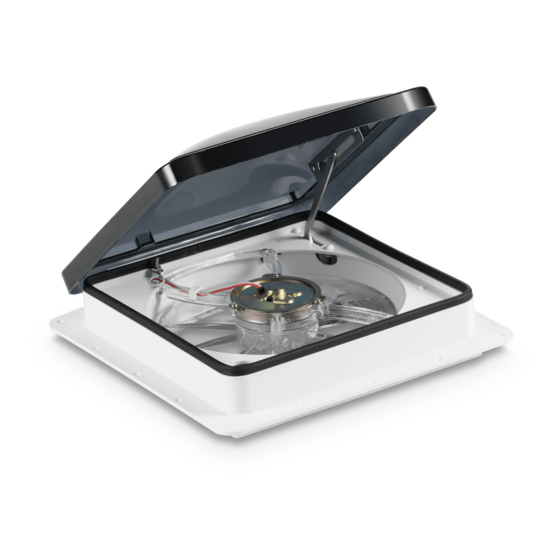
Page 10: Fan Motor Assembly
Dome Assembly Fan Motor Assembly Fan Blade Screw. Fan Base Screen Assembly Lift Motor Assembly Pop 'N Lock Screen Basic Automatic 12 Volt Hi-Power Vent (EXPLODED VIEW)
Need help?
Do you have a question about the 3350 and is the answer not in the manual?
Questions and answers