Advertisement
INSTALLATION AND OPERATION MANUAL
MANUAL DE INSTALACIÓN Y FUNCIONAMIENTO
INSTALLATIONS- UND BETRIEBSHANDBUCH
MANUEL D'INSTALLATION ET DE FONCTIONNEMENT
MANUALE D'INSTALLAZIONE E D'USO
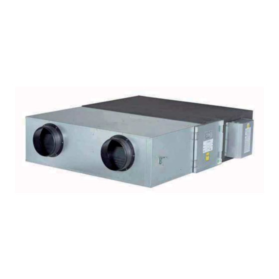
ENERGY RECOVERY VENTILATION UNITS
KPI-(252-2002)E4E & KPI-(502-1002)X4E
MANUAL DE INSTALAÇÃO E DE FUNCIONAMENTO
INSTALLATIONS- OG BETJENINGSVEJLEDNING
INSTALLATIE- EN BEDIENINGSHANDLEIDING
INSTALLATION- OCH DRIFTHANDBOK
Advertisement
Table of Contents

Related Manuals for Hitachi KPI-2002E4E


Summarization of Contents
GENERAL INFORMATION
General Notes
Standard disclaimers about documentation accuracy, copyright, and product changes.
Product Guide
Information on model identification, unit specifications, and pre-installation checks.
Safety Information
Essential safety warnings, symbols, and precautions for installation and operation.
Purpose of Manual
Outlines the scope and intended use of the installation and operation manual.
KPI UNITS INSTALLATION
Unit Installation
Detailed steps for mounting, positioning, and securing the KPI unit, including service space.
Duct and Filter Connection
Procedures for connecting air ducts and servicing suction air filters for optimal airflow.
Optional Functions and Setting
Configuration options for static pressure, ventilation modes, and increased air supply.
REFRIGERANT PIPING
Piping Connection
Instructions for connecting refrigerant pipes, including size specifications and flare pipe dimensions.
DRAIN PIPING
General Information
Guidelines for correct and incorrect drain piping installations, emphasizing slope and connections.
Drain Pipe Connection
Specific instructions for connecting the drain pipe, insulation, and syphon installation.
ELECTRICAL WIRING
Wiring Connection for KPI Unit
Steps for connecting power supply, remote control, and earth wires to the unit's electrical box.
DIP Switch Settings
Configuration of unit functions and model settings via DIP switches on PCB1 and PCB2.
Need help?
Do you have a question about the KPI-2002E4E and is the answer not in the manual?
Questions and answers