Hitachi airCore 700 Operation Installation Maintenance Manual
Hide thumbs
Also See for airCore 700:
- Operation installation maintenance manual (32 pages) ,
- Installation & maintenance manual (28 pages) ,
- Installation & maintenance manual (52 pages)
Table of Contents
Advertisement
Quick Links
Advertisement
Table of Contents

Related Manuals for Hitachi airCore 700


Summary of Contents for Hitachi airCore 700
- Page 1 – OPERATION INSTALLATION & MAINTENANCE MANUAL – SINGLE SPLIT INVERTER SERIES INDOOR UNITS MODELS HIGH ESP DUCTED TYPE PPIH-3.0UFA1NQ PPIH-4.0UFA1NQ PPIH-5.0UFA1NQ PPIH-6.0UFA1NQ PPIH-6.5UFA1NQ Scan the code to get the electronic manual. EN INSTRUCTION MANUAL P02131Q...
- Page 3 IMPORTANT NOTICE • Hitachi pursues a policy of continuous improvement in design and performance of products. The right is therefore reserved to vary specifications without notice. • Hitachi cannot anticipate every possible circumstance that might involve a potential hazard. •...
- Page 4 • This manual should be considered as a permanent part of the air conditioning equipment and should remain with the air conditioning equipment. DANGER • Do not install pipe work with diameters that are not specified for that model. • Do not ground units to water pipes, gas pipes, telephone wires, or lightning rods as incomplete grounding can cause a severe shock hazard resulting in severe injury or death.
- Page 5 • Before touching electrical parts, turn off the unit. • The circuit must be protected with safety devices in accordance with local and national codes, i.e. a circuit breaker. • Securely fasten the outdoor unit terminal cover (panel). If the terminal cover/panel is not installed properly, dust or water may enter the outdoor unit causing fire or electric shock.
- Page 6 Earth for Operating Line, Wired Controller and Remote Sensor Earth for Power Supply Line Power Supply Line Operating Line (Shielded Twist Pair Cable) Wired Controller and Remote Sensor (Shielded Twist Pair Cable) Fig.1 Earth Wiring NOTES: • The indoor unit should be positioned where the unit and interunit wires (outdoor to indoor) are at least 3.3ft (1m) away from any televisions or radios.
- Page 7 Precautions for R32 This air conditioner uses R32 flammable refrigerant. Air conditioner with R32 refrigerant, if not be treated carefully, may cause serious harm to the human body or surrounding things. Please read the following instructions carefully before installing, using and maintaining. WARNING •...
- Page 8 safety hazard. • Maintenance or repair of air conditioner using R32 refrigerant must be carried out after security check to minimize risk of incidents. • Ensure no following objects under the indoor unit: ○ Microwaves, ovens and other hot objects. ○...
- Page 9 • Anti-static precautions is necessary for installing and maintenance, for example, wear pure cotton clothes and gloves. • If R32 refrigerant leakage occurs during the installation, operators shall immediately detect the concentration in indoor environment until it reaches a safe level. If the leakage affects the performance of the machine, please immediately stop the operation, and the air conditioner must be vacuumed firstly and be returned to the maintenance station for processing.
- Page 10 ○ If a leakage of refrigerant is found which requires brazing, all of the refrigerant shall be recovered from the system, or isolated in a part of the system remote from the leak. Removal of refrigerant shall be according to this manual. •...
- Page 11 cylinders and the equipment are removed from site promptly and all isolation valves on the equipment are closed off. ○ Recovered refrigerant shall not be charged into another refrigerating system unless it has been cleaned and checked. • Equipment shall be labelled stating that it has been de-commissioned and emptied of refrigerant. The label shall be dated and signed.
- Page 12 Please contact your local agent, as the occasion arises. Hitachi’s liability shall not cover defects arising from the alteration performed by a customer without Hitachi’s consent in a written form.
-
Page 13: Table Of Contents
Table of Contents 1. Safety Summary .............................1 2. Structure .................................3 2.1 Name of Parts ............................3 2.2 Necessary Tools and Instrument List for Installation ................4 3. Transportation and Handling ........................4 3.1 Transportation ............................4 3.2 Handling of Indoor Unit ...........................4 4. Indoor Unit Installation ..........................5 4.1 Factory-Supplied Accessories ........................5 4.2 Initial Check ..............................6 4.3 Installation ..............................6... -
Page 14: Safety Summary
1. Safety Summary 1. Safety Summary DANGER • Do not perform the installation work, refrigerant piping work, drain pump, drain piping and electrical wiring connection without referring to our installation manual. If the instructions are not followed, it may result in a water leakage, electric shock or a fire. •... - Page 15 1. Safety Summary (a) The outdoor unit is not on an incline. (b) Abnormal sound does not occur. (c) The outdoor unit will not fall down due to a strong wind or earthquake. NOTICE • Make sure that the outdoor unit is not covered with snow or ice, before operation. •...
-
Page 16: Structure
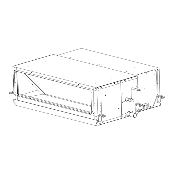
2. Structure 2. Structure 2.1 Name of Parts < PPIH-3.0UFA1NQ - PPIH-6.5UFA1NQ > Unit: mm Part Name Model PPIH-3.0UFA1NQ 1,076 1,000 Fan Motor PPIH-4.0UFA1NQ 1,076 1,000 Heat Exchanger PPIH-5.0UFA1NQ 1,300 1,240 Distributor PPIH-6.0UFA1NQ 1,300 1,240 Strainer PPIH-6.5UFA1NQ 1,300 1,240 Electrical Control Box Refrigerant Gas Pipe Connection Flange Dimension (H x W, mm) Refrigerant Liquid Pipe Connection... -
Page 17: Necessary Tools And Instrument List For Installation
3. Transportation and Handling 2.2 Necessary Tools and Instrument List for Installation Tool Tool Tool Handsaw Plier Cutter for Wires Phillips Screwdriver Pipe Cutter Gas Leak Detector Vacuum Pump Brazing Kit Leveler Refrigerant Gas Hose Hexagon Wrench Clamper for Solderless Terminals Megohmmeter Spanner Hoist (for Indoor Unit) -
Page 18: Indoor Unit Installation
4. Indoor Unit Installation 4. Indoor Unit Installation DANGER • Do not install the indoor unit in a flammable environment to avoid fire or an explosion. • Do not install the indoor unit in the laundry. • The indoor unit should be positioned in a place where: (1) both the air inlet and air outlet are unobstructed, (2) the unit is not exposed to direct sunlight, (3) drainage occurs easily,... -
Page 19: Initial Check
4. Indoor Unit Installation 4.2 Initial Check • Install the indoor unit with a proper clearance around it for operation and maintenance working space, as shown in Fig.4.1. Unit: mm 3.0HP-4.0HP 800 Min. 1000 Min. 1000 5.0HP-6.5HP 890 * In case that the ceiling board can not be detected for servicing, prepare a service access door below the indoor unit for removing the indoor unit. - Page 20 4. Indoor Unit Installation (1) Apply vibration absorbing mats (10t) under the indoor unit. < PPIH-3.0UFA1NQ - PPIH-6.5UFA1NQ > Vibration Absorbing View from Indoor Unit Mat (10t) Vibration Absorbing Mat (10t) Truss Wooden Bar Truss Wooden Bar Place the three wooden bars on the truss as shown in the figure. Note that the middle wooden bar should be placed in the center position of the unit.
- Page 21 4. Indoor Unit Installation (3) Remove the 4 bolts (M6) on the back of the supply air box, carefully pull the Return Air Box away, taking care not to damage the fan motor wiring (Fig.4.4). Heat Exchanger Compartment Return Air Box Rec eiver connector (for float switch and temp, sensors) Fig.4.4...
- Page 22 4. Indoor Unit Installation (2) Remove the 4 bolts (M6) on the back of the supply air box, carefully pull the Return Air Box away, taking care not to damage the fan motor wiring (Fig.4.7). Heat Exchanger Compartment Return Air Box Rec eiver connector (for float switch and temp, sensors) Fig.4.7...
- Page 23 4. Indoor Unit Installation 4.3.4 Suspension Bolts Step1 Select final location and installation direction of the indoor unit paying careful attention to the space for the piping, wiring and maintenance. Step2 Mount suspension bolts, as shown in Fig.4.9. *For Wooden Beam Suspension *For Concrete Slab *For Steel Beam Wooden Bar...
- Page 24 4. Indoor Unit Installation (1) How to put Nuts or Sling Bolts Put nuts on each of the four hanging bolts, as shown in Fig.4.12. Retaining Nut Indoor Unit Washer Fig.4.12 Sling Bolts and Nut (2) Hanging the Indoor Unit * Hook suspension bracket to the nut and washer of each hanging bolt, as shown, starting at the opposite side to service cover side.
-
Page 25: Refrigerant Piping Work
5. Refrigerant Piping Work (4) Perform the heat insulation work over the duct for dew protection. Silencer Canvas Duct Damper for Canvas Duct Silencer Adjusting Air Volume Thermal Insulation Indoor Unit Vibration Truss Keep Horizontal Absorbing Mat (10t) Wooden Bar Air Outlet Air Inlet Service Access Panel... - Page 26 5. Refrigerant Piping Work (1) Position of piping connection is shown below. Unit: mm Refrigerant Gas Pipe Connection Refrigerant Liquid Pipe Connection Drain Pipe Connection Fig.5.1 Position of Piping Connection Unit: mm (in. Model Gas Piping Liquid Piping PPIH-3.0UFA1NQ Φ12.7(1/2) Φ6.35(1/4) PPIH-4.0UFA1NQ PPIH-5.0UFA1NQ...
-
Page 27: Drain Piping
6. Drain Piping (4) Evacuation and refrigerant charging procedures should be performed according to “Installation & Maintenance Manual” of the outdoor unit. 6. Drain Piping (1) The position of the drain piping connection is shown in Fig.6.1. (2) Prepare polyvinyl chloride pipe with a 32mm outer diameter. (3) Fasten the tube to the drain hose with the adhesive agent and the factory-supplied clamp. -
Page 28: Electrical Wiring
7. Electrical Wiring 7. Electrical Wiring WARNING • Turn OFF the main power switch of the indoor unit and the outdoor unit and wait for more than 10 minutes before electrical wiring work or a periodical check is performed. • Check to ensure that the indoor fan and the outdoor fan have stopped before electrical wiring work or a periodical check is performed. - Page 29 7. Electrical Wiring Electrical Box Cover Air Inlet Remove the fixing screws for Electrical box cover. Ring Core Earth for Power Cord Earth for Transmission Cable Wired Remote Controller Power Cord Wired Remote Controller 220-240V~50Hz (Shielded Twist Pair Cable) Transmission Cable (Shielded Twist Pair Cable) Fig.7.1 Electrical Wiring Connection (Only for 3.0 - 4.0HP Models) Electrical Box Cover...
-
Page 30: Field Minimum Wire Sizes For Power Source
• The wire sizes marked with *2 in the table are selected at the maximum current of the unit according to the wire, MLFC (Flame Retardant Polyflex Wire) manufactured by Hitachi Cable Ltd., Japan. • Use a shielded cable for the transmitting circuit and connect it to ground. -
Page 31: Dip Switch Setting
7. Electrical Wiring 7.4 DIP Switch Setting 1. Turn OFF all the power supplies to both DSW3 DSW6 indoor and outdoor units before DIP DSW4 switch setting. Otherwise, the setting is DSW4 invalid. DSW3 DSW6 2. The positions of the DIP switches on the DSW9 DSW5 PCB are shown in the figure right. - Page 32 7. Electrical Wiring 7. Refrigerant cycle No. setting (DSW5) These switches set the refrigerant cycle number and need to be made only when connecting multiple systems together via H-Link (e.g. central control) DSW5 Refrigerant system setting Before delivery, DSW5 is set to “0”, a maximum of 64 indoor units can be connected.
-
Page 33: Setting Of External Static Pressure
8. Test Run 7.5 Setting of External Static Pressure (1) This function is available for airCore 700 ducted indoor units, please refer to the " chapter25.ESP Setting " of Installation & Maintenance Manual of the wired remote controller for details. -
Page 34: System Description
10. System Description 10. System Description The heat pump air conditioner is designed to offer cooling, heating, dry and fan operations. These operation modes are controlled by the remote control switch (optional). Table 10.1 Indoor Unit Type List Nominal Capacity (HP) Indoor Unit Type ○... -
Page 35: Before Operation
12. Before Operation 12. Before Operation CAUTION • Supply electrical power to the system for approximately 12 hours before start-up after long shut down. Do not start the system immediately after power supply, it may cause a compressor failure, because the compressor is not heated well. -
Page 36: Filter Cleaning
15. Filter Cleaning NOTE: • If the system is stopped due to a power failure, it will not automatically start again although power is restored. In the event of a very brief power failure (2 seconds maximum), the settings are memorized. Therefore, the system starts automatically after approximately 3 minutes. - Page 37 16. Troubleshooting • Dew on Air Panel When the cooling operation continues for a long period of time under high humidity conditions (Higher than 27°C/80% R.H.), dew can form on the air panel. • Refrigerant Flow Sound While the system is being started or stopped, sound from the refrigerant flow may be heard. NOTE: •...
- Page 38 Memo...
- Page 39 Memo...
- Page 40 Magnet Ring 1184066 Hitachi-Johnson Controls Air Conditioning, Inc. Add.: 1-16-1, Kaigan Minato-ku, Tokyo, Japan Specification in this catalogue are subject to change without notice, in order that Hitachi-Johnson Controls may bring the latest innovation to customers. 2023.10 Printed in China...
Need help?
Do you have a question about the airCore 700 and is the answer not in the manual?
Questions and answers