
Related Manuals for Eurotron MicroCal T500+


Summarization of Contents
APPENDIX
A1 EMC Conformity
Declaration of conformity for Electromagnetic Compatibility.
SPECIFICATIONS
1.1 MicroCal T100+
Technical specifications for the MicroCal T100+ model.
1.2 MicroCal T500+
Technical specifications for the MicroCal T500+ model.
1.3 MicroCal T1100+
Technical specifications for the MicroCal T1100+ model.
ORDERING CODE
2.1 MicroCal T100+
Ordering codes and options for the MicroCal T100+.
2.2 MicroCal T500+
Ordering codes and options for the MicroCal T500+.
2.3 MicroCal T1100+
Ordering codes and options for the MicroCal T1100+.
RECOMMENDATIONS
3.1 Position of the probe:
Guidelines for correct probe insertion into the calibrator block.
SAFETY INSTRUCTIONS
ADVICE FOR MICROCAL T100+
Specific advice for operating the MicroCal T100+ model.
PREPARATION
5.1 Installation
Steps for installing the calibrator and its components.
5.1.1 Removal of packaging
Instructions for unpacking the calibrator and its parts.
5.1.2 Positioning the calibrator
Guidance on placing the calibrator for optimal operation.
5.1.3 Supply
Details on power connection and voltage requirements.
5.1.4 Fitting the equalising block
Procedure for inserting the equalising block into the T1100+.
OPERATION PROCEDURE
6.1 Operation description
Overview of how the MicroCal T calibrator functions.
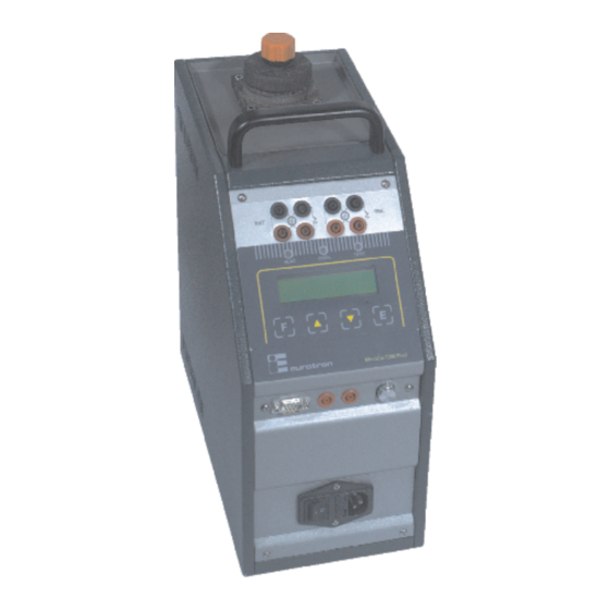
6.2 Description of instrument
Detailed explanation of the calibrator's components.
6.3 Start-up instructions
Procedures for safely starting up the calibrator.
6.4 Use of the function
Covers reading external probes, switch test, and serial communication.
6.5 Re-calibration methods
Guidelines for periodic re-calibration of the instrument.
REGULATOR
SP - Set Point
Setting the target temperature for the oven.
SP2 - Set Point 2
Setting the target temperature for ramp procedures.
GRAD - Gradient
Defining the temperature variation speed for ramps.
RAMP ON-OFF
Enabling or disabling ramp heating procedures.
RIS. 0.1/0.01
Setting the display reading resolution to 0.1°C or 0.01°C.
SW. ON / SW. OFF
Displaying thermostat contact status for switch tests.
SENSOR Configuration
Enabling reading of external sensors on auxiliary inputs.
P.B. - Proportional Band
Setting the proportional band for temperature regulation.
T.I. - Integral Time
Adjusting the integral time for temperature control.
T.D. - Derivative Time
Setting the derivative time for temperature control.
EXT SENSOR TYPE
Selecting the type of external sensor for input 1.
Units °C/°F
Choosing between Celsius and Fahrenheit for temperature display.
Def. Par. ON/OFF
Enabling or disabling default regulator parameter settings.
REF SENSOR TYPE
Selecting the type of reference sensor for input 2.
KEY Parameter
Accessing the third programming level for configuration.
ACCESS KEY
Setting the access key for the third programming level.
BAUD RATE
Configuring the data transmission speed for computer communication.
ADDRESS
Setting the communication address for instrument control.
S/N
Equipment serial number, set by manufacturer.
STANDARD SYSTEM
Indicates if system is heat-only or Peltier.
MAX. SET.
Maximum settable value for Set Point.
MIN. SET.
Minimum settable value for Set Point.
WAIT 0/1
Configuring the initial waiting procedure upon startup.
REV. SOFTWARE
Internal software release number.
SENSOR TYPE
Indicates the main sensor type for temperature adjustment.
STAB: +/-0,25°C
Indicates temperature stability and steadiness.
WARRANTY
10.1 Warranty terms
Conditions and limitations of the product warranty.
10.2 Letter of conformity
Document confirming instrument conformity to standards.
Need help?
Do you have a question about the MicroCal T500+ and is the answer not in the manual?
Questions and answers