Table of Contents
Advertisement
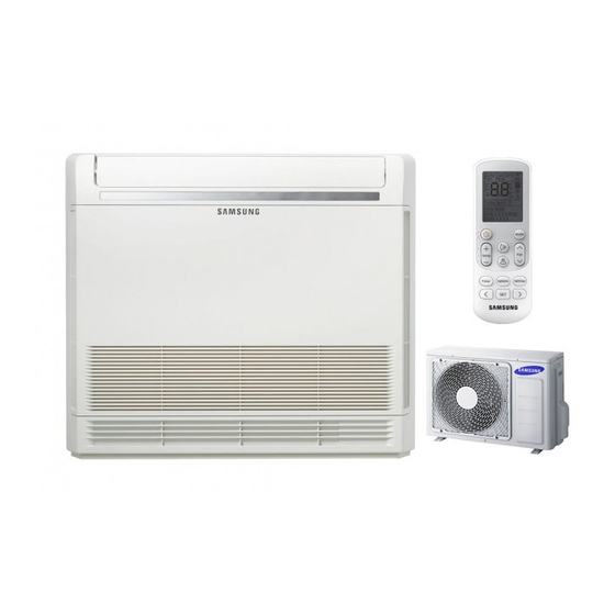
AIR CONDITIONER
AC026FBJDEH/EU
AC026FBJDEH/EU
AC035FBJDEH/EU
AC035FBJDEH/EU
AC052FBJDEH/EU
AC052FBJDEH/EU
AC026FCADEH/EU
AC035FCADEH/EU
AC052FCADEH/EU
Refer to the service manual in the GSPN(see the rear cover) for the more information.
SYSTEM AIR CONDITIONER
BASIC MODEL : JH052EAV1 / RC052DHXEA
MODEL : AC026FBJDEH / AC026FCADEH
AC035FBJDEH / AC035FCADEH
AC052FBJDEH / AC052FCADEH
MODEL CODE :
AC026FBJDEH / EU / AC026FCADEH / EU
AC035FBJDEH / EU / AC035FCADEH/ EU
AC052FBJDEH/ EU / AC052FCADEH/ EU
CONTENTS
1. Precautions
2. Product Specifications
3. Disassembly and Reassembly
4. Troubleshooting
5. PCB Diagram
6. Wiring Diagram
7. Schematic Diagram
8. Reference Sheet
Advertisement
Table of Contents
Troubleshooting

Related Manuals for Samsung AC035FBJDEH


Summarization of Contents
Safety and Precautions
1-1 Precautions for the Service
Safety guidelines for service personnel during repairs and maintenance.
1-3 Precautions related to product safety
Critical safety measures to prevent electric shock, fire, and other hazards.
Product Specifications and Accessories
2-1 The Feature of Product
Overview of unique features and technologies of the air conditioner.
2-2 Product Specifications
Detailed technical data, dimensions, capacity, and power requirements for different models.
2-3 Product Accessories
Lists of included accessories and optional items for the air conditioner.
Disassembly and Reassembly
Necessary Tools
Essential tools required for disassembling and reassembling the air conditioner components.
3-1 Indoor unit
Step-by-step procedure for safely disassembling the indoor unit.
3-2 Outdoor unit
Step-by-step procedure for safely disassembling the outdoor unit.
Troubleshooting and Diagnostics
4-1 Setting an indoor unit address and installation option
Guide to setting indoor unit addresses and installation options via remote control.
4-2 Item to check before diagnosis
Preliminary checks and error code interpretation for diagnosing issues.
4-3 Troubleshooting by symptoms (Indoor Unit)
Detailed troubleshooting for common indoor unit errors like sensor issues and fan problems.
4-4 Troubleshooting by symptoms (Outdoor Unit & Errors)
Troubleshooting for outdoor unit errors, communication issues, and component failures.
PCB Diagram
5-1 PCB Diagram
Visual representation of the printed circuit board layouts for indoor and outdoor units.
5-1-2 Display PCB
Detailed diagram of the display board components and connections.
5-1-4 Outdoor Unit PCB
Layout and connector information for the outdoor unit's main printed circuit board.
Wiring Diagram
6-1 Indoor Unit Wiring Diagram
Electrical connection diagram for the indoor unit components.
6-2 Outdoor Unit Wiring Diagram
Electrical connection diagram for the outdoor unit components.
Schematic Diagram
7-1 Indoor Unit Schematic Diagram
Detailed circuit schematics for the indoor unit's main PCB.
7-2 Out Unit Schematic Diagram
Detailed circuit schematics for the outdoor unit's main PCB.
Reference Sheet
8-1 Index for Model Name
Guide to understanding model codes and their corresponding specifications.
8-2 Refrigerating Cycle Diagram
Diagram illustrating the flow of refrigerant through the air conditioning system.
Need help?
Do you have a question about the AC035FBJDEH and is the answer not in the manual?
Questions and answers