Samsung AC052HBLDKH Service Manual
Hide thumbs
Also See for AC052HBLDKH:
- User manual (21 pages) ,
- Manual (53 pages) ,
- Installation instructions manual (35 pages)
Table of Contents
Advertisement
AIR CONDITIONER
AC035HCADKH
AC052HCADKH
SYSTEM AIR CONDITIONER
Model :
Model Code :
AC035HBMDKH
AC052HBMDKH
AC052HBLDKH
AC071HBLDKH
AC060HBMDKH
AC071HBMDKH
AC060HCADKH
AC071HCADKH
Indoor Unit
Outdoor Unit
AC052HBLDKH AC052HCADKH
AC071HBLDKH AC071HCADKH
AC035HBMDKH AC035HCADKH
AC052HBMDKH AC052HCADKH
AC060HBMDKH AC060HCADKH
AC071HBMDKH AC071HCADKH
AC052HBLDKH/EU AC052HCADKH/EU
AC071HBLDKH/EU AC071HCADKH/EU
AC035HBMDKH/EU AC035HCADKH/EU
AC052HBMDKH/EU AC052HCADKH/EU
AC060HBMDKH/EU AC060HCADKH/EU
AC071HBMDKH/EU AC071HCADKH/EU
CONTENTS
1. Precautions
2. Product Specifications
3. Disassembly and Reassembly
4. Troubleshooting
5. PCB Diagram
6. Wiring Diagram
7. Reference Sheet
Advertisement
Table of Contents
Troubleshooting

Related Manuals for Samsung AC052HBLDKH


Summary of Contents for Samsung AC052HBLDKH
- Page 1 SYSTEM AIR CONDITIONER Indoor Unit Outdoor Unit Model : AC052HBLDKH AC052HCADKH AC071HBLDKH AC071HCADKH AC035HBMDKH AC035HCADKH AC052HBMDKH AC052HCADKH AC060HBMDKH AC060HCADKH AC071HBMDKH AC071HCADKH Model Code : AC052HBLDKH/EU AC052HCADKH/EU AC071HBLDKH/EU AC071HCADKH/EU AC035HBMDKH/EU AC035HCADKH/EU AC052HBMDKH/EU AC052HCADKH/EU AC060HBMDKH/EU AC060HCADKH/EU AC071HBMDKH/EU AC071HCADKH/EU AIR CONDITIONER CONTENTS 1. Precautions AC035HBMDKH 2.
-
Page 2: Table Of Contents
Contents 11. Precautions ............................1-1 Precautions for the Service ......................1-2 Precautions for the Static Electricity and PL ................1-3 Precautions for the Safety ....................... 1-4 Others ..............................12. Product Specifications ....................... 2-1 The Feature of Product ........................2-2 Product Specifications ........................ -
Page 3: Precautions
- Release the valve caps on High and Low pressure side. - Use L wrench to close the valve on the high pressure side. - Approximately 2 minutes after, close the valve on the low pressure side. - Stop operation of the air conditioner. - Disconnect the pipes. Samsung Electronics... -
Page 4: Product Specifications
It can give the benefit to the installers and aries the reliability of the air conditioner. ■ Long Ambient Operation (In Low Temperature) It can arise the reliability and the capacity of the air conditioner, especially operated in low temperature. ■ Eco-friendly Product (Lead-Free, RoHS, WEEE) Samsung Electronics... -
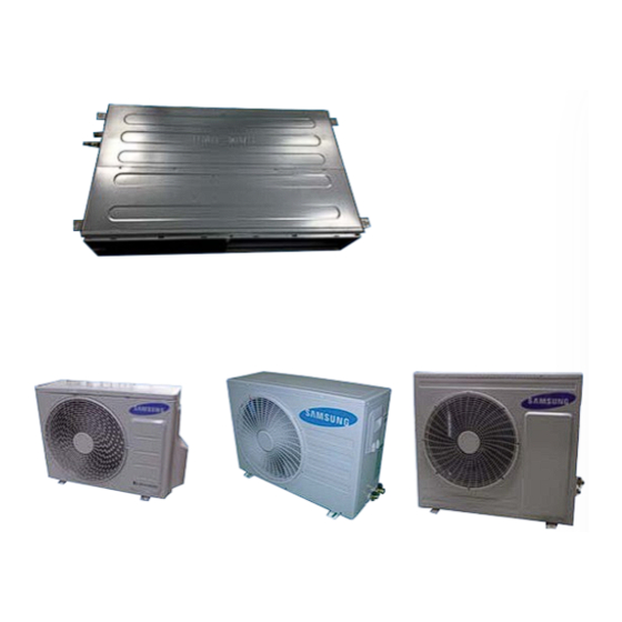
Page 5: Product Specifications
2-2 Product Specifications AC052HBLDKH AC071HBLDKH ITEM AC052HCADKH AC071HCADKH Indoor Unit Outdoor Unit IMAGE MWR-WE10 MWR-WE10 Remote Controller Power Product 1Φ, 220~240V/50Hz 1Φ, 220~240V/50Hz Indoor L x H x D 1100*200*450 1100*200*450 Outdoor L x H x D 880*638*310 880*798*310 Indoor... - Page 6 Noise (Cooling/Heating) In case of strongest air Outdoor unit blow Refrigerant (R410A) 1300 Liquid 1/4"(6.35) 1/4"(6.35) Connecting Pipe 3/8"(9.52) 1/2"(12.7) Additional Refrigerant (R410A) Standard Extension length(Total) Extension length(Elevation) Product Option 01B06C-1C5552-272328-374000 01B06C-1C55A4-27323C-373000 Option Code Installation Option 020000-100000-200000-300000 020000-100000-200000-300000 Samsung Electronics...
- Page 7 (Cooling/Heating) In case of strongest air Outdoor unit blow Refrigerant (R410A) 1500 1500 Liquid 1/4"(6.35) 1/4"(6.35) Connecting Pipe 5/8"(15.88) 5/8"(15.88) Additional Refrigerant (R410A) Standard Extension length(Total) Extension length(Elevation) Product Option 01B06C-1C592B-273C46-372005 01B06C-1C593C-274750-371005 Option Code Installation Option 020000-100000-200000-300000 020000-100000-200000-300000 Samsung Electronics...
-
Page 8: Accessory
Insu DRAIN HOSE DB62-11028A 1/1/1 INSU HOSE D DB62-11028E Indoor Unit INSU TUBE OUT DB62-11028F ASSY DRAIN HOSE JOINT DB67-01191A Ass'y Drain Hose Joint DB90-06701A GROMMET-HANGER DB63-00237A RUBBER LEG DB73-20134A INSTALLATION MANUAL DB68-04465A Outdoor unit DRAIN PLUG DB73-20134A Samsung Electronics... -
Page 9: Disassembly And Reassembly
3. Disassembly and Reassembly ■ Necessary Tools Item Remark +SCREW DRIVER MONKEY SPANNER Samsung Electronics... -
Page 10: Indoor Unit
Motor 1)Disassemble the Cabinet Bottom Fan. & - Unscrew 10 screws Blower 2)Disassemble the Case Filter Pre. 3)Disassemble the 2 Case Blower Bottom. - Unscrew 4 screws 4)Disassemble the Cover Control. - Unscrew 2 screws 5)Cut the cable-tie Samsung Electronics... - Page 11 7)Disassemble the 2 Holder Motor. - Unscrew 2 screws 8)After disassembling the Motor and Blower for the set, disassemble the Blower by use of 3mm wrench. 9)Disassemble the both of Case Blower Out - Unscrew 4 screws Samsung Electronics...
- Page 12 1)Disassemble the Cabinet Bottom Evap. - Unscrew 7 screws 2)Pull the Drain Pan Out EVAP 1)Disassemble the Support Evap. - Unscrew 1 screws 2)Disassemble the Cover Pipe. - Unscrew 2 screws 3)Disconnect the wire betwwen assy control out and Evap Samsung Electronics...
- Page 13 Parts Procedure Remark 4)Disassemble the Evap. - Unscrew 3 screws. Then pull the Evap out Cushion 1)Pull out the Cushion 2)Disassemble the Seal Cushion LF. - Unscrew 1 screws 3)Disassemble the Assy Cushion Right. - Unscrew 1 screws Samsung Electronics...
- Page 14 Case Blower&Bracket 1)Disassemble the both of Case Blower Out Motor - Unscrew 4 screws 2)Disassemble the Bracket Motor. - Unscrew 6 screws Control 1)Disassemble the Case Control. - Unscrew 2 screws Frame 1)Disassemble the Frame. - Unscrew 6 screws Samsung Electronics...
- Page 15 ■ AC052HBLDKH/ AC071HBLDKH Parts Procedure Remark Motor 1)Disassemble the Cabinet Bottom Fan. & - Unscrew 10 screws Blower 2)Disassemble the Case Filter Pre. 3)Disassemble frame-up - Unscrew 2 screws 4)Disassemble the case blower - Unscrew 3 screws 5)Disassemble cover control...
- Page 16 7)Disassemble the 2 Holder Motor. - Unscrew 2 screws 8)After disassembling the Motor and Blower for the set, disassemble the Blower by use of 3mm wrench. 9)Disassemble the both of Case Blower Out - Unscrew 6 screws Samsung Electronics...
- Page 17 - Unscrew 7 screws 2)Pull the Drain Pan Out EVAP 1)Disassemble the Cover Pipe. - Unscrew 2 screws 2)1)Disassemble the Support Evap and hold evap. - Unscrew 3 screws 3)Disconnect the wire betwwen assy control out and Evap Samsung Electronics...
- Page 18 Parts Procedure Remark 4)Then pull the Evap out Cushion 1)Pull out the seal Cushion front 2)Disassemble the Seal Cushion Right. - Unscrew 1 screws 3)Disassemble the Assy Cushion LF. - Unscrew 1 screws 3-10 Samsung Electronics...
- Page 19 1) Loosen 2 screws of Assy control in and Remove the assy control in. 2) Remove wires from wire saddle. 3) clip cable tie. (It is necessary to re-tie “cable tie” on re- assembly,then place in wire saddle .) Samsung Electronics 3-11...
- Page 20 Parts Procedure Remark Frame 1)Disassemble the Frame. - Unscrew 4 screws 3-12 Samsung Electronics...
-
Page 21: Outdoor Unit
1) loosen 1 pcs screw of cover control,and detach it. 2) loosen 5 pcs screws on both right and left cabniet side edges and to detach the cover-top 3) Loosen 7 screwsfixed to disassemble cabi-front , and detach it. Samsung Electronics 3-13... - Page 22 Parts Procedure Remark common work 4) loosen 7 screws to disassemble the cabi- right ,and detach it. 5) loosen 2 screws to disassemble steel-bar. 6) loosen 3 screws to disassemble cabi-left. 3-14 Samsung Electronics...
- Page 23 Remark fan&motor 1) loosen 1 screw as indication and detached the fan. 2) loosen 4 pcs motor screws and disconnect the wire betwwen assy control out and motor. 3) loosen 2 pcs bracket-motor screw and detach it. Samsung Electronics 3-15...
- Page 24 Heat exchanger 1) Release the refrigerant at first 2) Looosen fixing screw on both side. 3) disaessembly the pipes in both inlet and outlet with welding torch. 4) detach the heat exchanger. 3-16 Samsung Electronics...
- Page 25 2)disassembly the felt comp sound. loosen the 3 bolts at the bottom . When removing the compressor, CAUTION Heat Exchanger, and Pipe, purge the Coolant inside the Compressor complete- ly and remove the pipe with a welding flame. Samsung Electronics 3-17...
- Page 26 1) Loosen 1 pcs screw of cover control 2) Loosen 8 pcs screw of the cabi top cover. 3) Loosen 9 pcs screw of the cabi side right 4) Loosen 7 pcs screw of the cabi side front. 3-18 Samsung Electronics...
- Page 27 Parts Procedure Remark common work Fan& motor 1) Loosen the fan screw according the indication and detach the fab propeller 2)Disconnect the wire between assy control out and motor. 3) Loosen 4 pcs motor screw. Samsung Electronics 3-19...
- Page 28 Parts Procedure Remark 4) Loosen 2 pcs screw of bracket motor. Assy control out 1)Loosen the screws that connected partition and case control then get the control out. 2) Loosen the screw of the cover termimal 3-20 Samsung Electronics...
- Page 29 4) Detach the heat exchanger. When removing the compressor, CAUTION Heat Exchanger, and Pipe, purge the Coolant inside the Compressor complete- ly and remove the pipe with a welding flame. Compressor 1)Loosen the 3 bolts at the bottom of com- pressor. Samsung Electronics 3-21...
- Page 30 1) Loosen 1 pcs screw of cover control 2) Loosen 8 pcs screw of the cabi top cover. 3) Loosen 13 pcs screw of the cabi side right 4) Loosen 9 pcs screw of the cabi side front. 3-22 Samsung Electronics...
- Page 31 Parts Procedure Remark common work Fan& motor 1) Loosen the fan screw according the indication and detach the fab propeller 2)Disconnect the wire between assy control out and motor. 3) Loosen 4 pcs motor screw. Samsung Electronics 3-23...
- Page 32 Parts Procedure Remark 4) Loosen 4 pcs screw of bracket motor. Assy control out 1)Loosen the screws that connected partition and case control then get the control out. 2) Loosen the screw of the cover termimal 3-24 Samsung Electronics...
- Page 33 4) Detach the heat exchanger. When removing the compressor, CAUTION Heat Exchanger, and Pipe, purge the Coolant inside the Compressor complete- ly and remove the pipe with a welding flame. Compressor 1)Loosen the 3 bolts at the bottom of com- pressor. Samsung Electronics 3-25...
- Page 34 3-26 Samsung Electronics...
-
Page 35: Troubleshooting
(Communication error for more than 2 minutes) Flickering X Off If you turn off the air conditioner when the LED is flickering, the LED is also turned off. Samsung Electronics... -
Page 36: Wired Remote Controller
3minutes. Error of communication down between the indoor unit Wired remote and wired remote controller after completion of 10 times tracking. controller error COM1/COM2 Cross-installed error Error of master wired remote controller and slave wired remote controller setting Samsung Electronics... -
Page 37: Outdoor Trouble Shooting
3. Check if there's any blockage on refrigerant cycle (indoor unit/outdoor unit) 4. Check if additional refrigerant has been added after pipe extension Outdoor EEPROM checksum error between MAIN and INVERTER. Check Outdoor Inverter PBA E590 | Off € Blink z On Samsung Electronics... -
Page 38: Setting Option Setup Method
You can only check the indoor unit option code in Slave wired remote controller. Setting indoor unit option code is possible when one indoor unit is connected. If more than 2 indoor units are connected, you can only check the Master indoor unit option code. Samsung Electronics... -
Page 39: Setting An Indoor Unit Address And Installation Option
Press the button anytime during setup to exit without setting. NOTE Address will not be applied if you don't press button. Setting Main/RMC Address of an Indoor unit is available only with a master wired remote controller. Samsung Electronics... - Page 40 Drain pump RESERVED RESERVED RESERVED Master / Slave SEG13 SEG14 SEG15 SEG16 SEG17 SEG18 External control Number of hours External control Virus doctor Buzzer output using filter SEG19 SEG20 SEG21 Individual control Heating setting of a remote compensation controller Samsung Electronics...
- Page 41 Option code will not be applied if you don't press button. Setting Installation option code is available only with a master wired remote controller. Setting Installation option code is available when there is one on one connection between a wired remote controller and an indoor unit. Samsung Electronics...
- Page 42 2.5< SP <5 01B06C-1C50EB-272328-374000 5≤ SP <7.5 01B06C-1C5552-272328-374000 7.5≤ SP ≤10 01B06C-1C55CA-272328-374000 10< SP <12.5 01B06C-1C5A30-272328-374000 12.5≤ SP ≤15 01B06C-1C5A85-272328-374000 Model AC052HBLDKH AC071HBLDKH Static Pressure(mmAq) Option code for indoor unit 0≤ SP ≤3 01C06C-1C5925-27323C-370000 01C06C-1C59E8-274750-370000 3< SP <4 01C06C-1C596B-27323C-370000 01C06C-1C5D2D-274750-370000 Model...
-
Page 43: Items To Be Checked First
The compressor operates in a reverse cycle to remove Indoor fan and outdoor fan stop operation intermittently exterior ice in a HEAT mode, and indoor fan and outdoor in a HEAT mode. fan do not operate intermittently for within 20% of the total heater operation Samsung Electronics... -
Page 44: Fault Diagnosis By Symptom
Wrong setting Check DIP SW in the Set DIP SW correctly wired remote controller. Correct Is there any error display on Check each item according to error code list the wired remote controller Check the setting temperature 4-10 Samsung Electronics... - Page 45 #1 and #3 Are wire and socket connected correctly? CN05,06,07 TAB terminal(EMI PCB), Check and correct the wiring Error 469 display Error 469 display CN20(INVERTER PCB) (Table No.19) (Table No.19) Check the M/C Samsung Electronics 4-11...
- Page 46 Is the Pin voltage #6 - #3 of CN40 and 41 changed high(4-5V) and low(0-1V) in case of Exchange INVERTER PCB making manual rotation slowly? Is the Pin voltage #7 - #3 of CN40 and Exchange the FAN motor 41 low(0-1V) in normal rotation? Exchange INVERTER PCB 4-12 Samsung Electronics...
- Page 47 Does the compressor rotate normally? Exchange the compressor Are the service valves full opened? Open valve screw to the end. Is AC power voltage normal during the Check AC power source compressor in operation? Exchange INVERTER PCB Samsung Electronics 4-13...
- Page 48 4-WAY valve coil error of 4-WAY valve coil. Dose the voltage of AC220V Exchange apply to the connector of 4-WAY the outdoor PCB. valve coil during the operation? Go to the next page 4-WAY valve main body error 4-14 Samsung Electronics...
- Page 49 Connect the connector. correctly? Check the resistance value Outdoor fan error of outdoor fan. Dose the voltage of DC300V apply to the connector of outdoor Check the motor wire. fan during the operation of outdoor unit? Outdoor PCB error Samsung Electronics 4-15...
-
Page 50: Outdoor Temperature Sensor Error
Exchange the sensor. (Refer to the R/T TABLE) Is the resistance value of sensor connection pull_up 18K? Exchange the PCB. Exchange the PCB. Normal operation Exit 400.0 350.0 300.0 250.0 200.0 150.0 100.0 50.0 4-16 Samsung Electronics... - Page 51 Exchange the sensor. (Refer to the R/T TABLE) Is the resistance value of sensor connection pull_up 24K? Exchange the PCB. Exchange the PCB. Normal operation Exit 600.0 500.0 400.0 300.0 200.0 100.0 Samsung Electronics 4-17...
- Page 52 Exchange the sensor. (Refer to the R/T TABLE) Is the resistance value of sensor connection pull_up 18.2K? Exchange the PCB. Exchange the PCB. Normal operation Exit 400.0 350.0 300.0 250.0 200.0 150.0 100.0 50.0 4-18 Samsung Electronics...
- Page 53 1) Is the connection of R, S, T power wire normal? 2) Are Relay RY21 and R200 on the INVERTER PCB mounted normally? 2. Troubleshooting procedure Are connection of the wire from INVERTER PBA to Check and correct the wire connection EMI PBA normal? Exchange INVERTER PCB Samsung Electronics 4-19...
- Page 54 Is insuration resistance between each Exchange the compressor compressor terminal and body normal? Does the compressor rotate normally? Exchange the compressor Did AC power voltage interruption happen Check AC power source during the compressor in operation? Exchange INVERTER PCB 4-20 Samsung Electronics...
-
Page 55: Communication Error
Is the communication error Terminate the service. occurred again? Isn't the power cable and Correct the wrong wiring. communication cable wiring error? Is the connection of Correct the connection of communication cable normal? communication cable. Exchange the outdoor unit PCB. Samsung Electronics 4-21... - Page 56 Exchange the compressor. compressor(u v, v w, w u) normal? Is the compressor body and Exchange the compressor. interphase resistance insulated? Is the connection cable for the Correct the cable connection. compressor and power terminal normal? Exchange the PCB. 4-22 Samsung Electronics...
- Page 57 Exchange the compressor. compressor(u v, v w, w u) normal? Is the compressor body and Exchange the compressor. interphase resistance insulated? Is the connection cable for the Correct the cable connection. compressor and power terminal normal? Exchange the PCB. Samsung Electronics 4-23...
- Page 58 Exchange INVERTER PCB The cause of this error may be power source trou- ble as like power interruption. Check the power source. 4-5-16 The others 1. Capacity miss match – Check again the indoor unit option code. 4-24 Samsung Electronics...
-
Page 59: Pcb Inspection Method
● EMI PCB part : Line filter for electrical noise, Varistors for surge and Fuses. ● MAIN PCB part : Refrigeration cycle controller with MICOM ● INVERTER PCB part : Compressor driving inverter and BLDC fan controller Samsung Electronics 4-25... - Page 60 FAN operation checking 1) Is the FAN motor running? Controller trouble inside of the fan motor Press the ON/OFF button. 2) Is the connection of CN73 normal? connector trouble of CN73 1. FAN Speed[HIGH] 2. FAN mode 4-26 Samsung Electronics...
- Page 61 D101 upper side pin of '~' marking pins INVERTER PCB 2) Is DC Link voltage 450-510V? Check IGBT module pins marking voltage near C701 Check BLDC fan 1) See 12-2-3 The Outdoor unit Fan error(Fault Diagnosis) Samsung Electronics 4-27...
-
Page 62: Troubleshooting By Symptoms
10.00 12.10 14.70 In this case, is the resistance 18.00 value out of range in the temperature 22.00 table on the right? 28.30 33.90 Indoor temperature sensor 42.30 failure (replace) Restart the system after replacing the PCB 4-28 Samsung Electronics... - Page 63 4.160 5.828 8.313 12.09 In this case, is the resistance 17.95 value out of range in the temperature 27.27 table on the right? 42.42 67.72 EVA sensor failure (replace) 111.2 Restart the system after replacing the PCB Samsung Electronics 4-29...
- Page 64 PCB?(CN301) Connect the connector to PCB and restart the unit Is there foreign substance stuck in the motor fan? Remove the foreign substance and restart the unit Replace the PCB and restart the unit 4-30 Samsung Electronics...
- Page 65 Remove the wire connector from the PCB and measure the resistance between two terminals Is the resistance 0Ω ? Replace the Terminal Block and restart the unit Replace the PCB and restart the unit Samsung Electronics 4-31...
- Page 66 X (Defrost) X (Timer) (Fan) (Filter) Wire remote controller display E422 Clogging of outdoor's service valve Symptom Failure Valve clog Is the outdoor service valve clogging? Open the outdoor's service valve Replace the PCB and restart the unit 4-32 Samsung Electronics...
- Page 67 Remove the wire connector from the PCB and measure the resistance between two terminals Is the resistance 0Ω ? Replace the float switch and restart the unit Replace the PCB and restart the unit Samsung Electronics 4-33...
-
Page 68: Eeprom Error
MAIN PCB?(CN201) Connect the EEPROM PCB to MAIN PCB and restart the unit Connect the EEPROM PCB to MAIN PCB Is the error mode disappear ? Replace the PCB and restart the unit The indoor unit work normaly 4-34 Samsung Electronics... - Page 69 Wire remote controller display E163 Symptom EEPROM option setting error Option error Failure Input the right option to EEPROM PCB Is the error mode disappear ? Replace the PCB and restart the unit The indoor unit work normaly Samsung Electronics 4-35...
-
Page 70: Main Part Inspection Method
10KΩ ~ 50KΩ reverse Abnormal 0Ω...Open or Short Outdoor Unit 4way Valve Solenoid Measure resistance with a multimeter Normal At the normal temperature(10˚C~30˚C) 1.6KΩ±15% ∞,0Ω...Open or Short Abnormal Remark : 4-5-4~7 contents are for heat pump model (DH18/24BT) . 4-36 Samsung Electronics... -
Page 71: Pcb Diagram And Parts List
3711-000795 CN804 SMW250-02 BLU 3711-001036 CN808 SMW250-06 BLU 3711-004182 CN905 FAN MOTOR COMM SMW200-10P WHT 3711-003895 CN501 DISPLAY SMW200-13P WHT 3711-000794 CN411 FLOAT-SW SMW250-02 BLK 3711-000015 CN412 ROOM SENSOR SMW250-02 WHT 3711-004236 CN413 EVA DIS/OUT SENSOR SMW200-06P WHT Samsung Electronics... - Page 72 AC052HBLDKH / AC071HBLDKH Description Description Description 1.CN103-DRAIN 10.CN412-ROOM 15.CN311-2WIRE #1:POWER #1:ROOM #1:12V #2:GND #2:GND #2:COM2_PCTRL_MICOM 2.CN413-EVA DIS/OUT/IN #3:COM2_VCHECK_A 11.CN501-DISPLAY #1:EVA-IN #4:COM2_VCHECK_B #1:12V #3:EVA-OUT #2~#6:DISPLAY LED CONTROL #5:COM2_MICOM_AD #6:VCC #5:DISCHARGE #7:BZ_1 #8:REMOCON SIGNAL OUT #7:COM2_ENABLE #2,#4,#6:GND #8:COM2_C #9:AUTO_SW 3.CN140-FUSE CHK #10:REMOCON_INT...
- Page 73 SUB PBA POWER:SMW200-05P BLK EEV1:SMW250-05 RED COMP:DBT061-3P WHT SMPS: SMW250-03 BLU EEPROM:B7P-MQ WHT TEMP SENSOR: SMW200-08P WHT MAIN DOWNLOAD:YDW200-20 BLK SUB PBA: SMW200-10P BLK DRED:SMW250-05 WHT INV DOWNDOWN: YDAW200-20TR BLK SUB PBA: SMW200-10P WHT ENABLE CGND: SMW250-03 RED Samsung Electronics...
- Page 74 4WAY:YW396-03AV WHT COMM:YW396-02V RED TEMP SENSOR: SMW200-08P WHT DRED:SMW250-05 WHT SUB PBA: SMW200-10P WHT SUB PBA: SMW200-10P BLK EEV1:SMW250-05 RED SMPS: SMW250-03 BLU EEPROM:B7P-MQ WHT MAIN DOWNLOAD:YDW200-20 BLK BLDC FAN:YAW396-06V WHT ENABLE CGND: SMW250-03 RED INV DOWNDOWN: YDAW200-20TR BLK Samsung Electronics...
-
Page 75: Wiring Diagram
6. Wiring Diagram 6-1 Indoor Unit AC052HBLDKH / AC071HBLDKH This Document can not be used without Samsung’s authorization. Samsung Electronics... - Page 76 AC035HBMDKH / AC052HBMDKH / AC060HBMDKH / AC071HBMDKH This Document can not be used without Samsung’s authorization. Samsung Electronics...
-
Page 77: Outdoor Unit
6-2 Outdoor Unit AC035HCADKH This Document can not be used without Samsung’s authorization. Samsung Electronics... - Page 78 AC052HCADKH / AC060HCADKH / AC071HCADKH This Document can not be used without Samsung’s authorization. Samsung Electronics...
-
Page 79: Refrigerating Cycle Diagram
You can open the valve by turning the need valve counterclockwise using hex wrench, and it is used for vacuum, gas purging, coolant injection, coolant purging, and indoor-outdoor unit connection. ACCUMULATOR Accumulator prevents the flow of liquid-state coolant into the compressor. (Liquid-state coolant flowing into the compres- sor will overload the compressor.) Samsung Electronics... -
Page 80: Index For Model Name
->4Way : 4 , MSP Duct : DUCT STANDARD+GENERAL (In/ M , Ceiling : C Temp.+NON MODULE CEILING out) STANDARD CONSOLE DELUXE + TROPICAL FLOOR MOUNTING ※ "/" can be removed from the buyer card if there are not enough digits. Samsung Electronics... - Page 82 This Service Manual is a property of Samsung Electronics Co., Ltd. © Samsung Electronics Co., Ltd Jan. 2014. Any unauthorized use of Manual can be punished under applicable Printed in China. International and/or domestic law. Code No. DB68-04356C (1)
Need help?
Do you have a question about the AC052HBLDKH and is the answer not in the manual?
Questions and answers