Advertisement
SERVICE
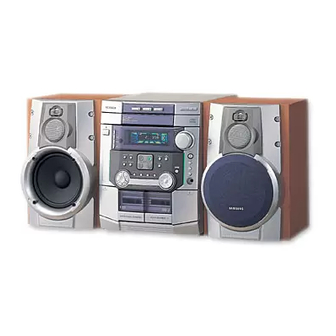
MIMI MIMI COMPONENT SYSTEM
-- Disc Selection / Direct Play --
Disc 1
On/Standby
Demo
PTY
RDS
Display
Timer
/Clock
Preset/
Mono/ST
Memory
Deck 1/2
REV.Mode
REC/Pause
Down
Up
Tuning Mode
3 VCD CHANGER
MINI MINI COMPONENT
MAX-WL69/ZL65/L68/L65/L67
Disc 2
Disc 3
Disc Change
Volume
+
_
Power
Surround
CD
Program
Repeat
TUNER
CD
Band
S.BASS
D / P / S
DIRECT PLAY & SELECTION
Shuffle
E Q
TAPE
AUX
Enter
D.S.P
CD
Dubbing
Synchro
Normal
HI - Speed
Phones
CD-R/RW PLAYBACK
Manual
CONTENTS
2. Exploded Views and Parts List
5. PCB Diagrams
Advertisement

Related Manuals for Samsung MAX-L68


Summarization of Contents
Service Manual Alignment Procedures
Tuner Alignment and Adjustment Guide
Details FM and AM tuner adjustments, including THD, Search Level, and IF levels.
Cassette Deck Calibration and Adjustment
Covers tape speed, REC bias voltage, L/R unbalance, and playback/REC levels.
System Block Diagrams
Main System Block Diagram
Illustrates the overall system connectivity and major functional blocks on the main PCB.
CD Mechanism Block Diagram
Shows the signal flow and components within the CD mechanism and its control.
Circuit Schematics
CD/MP3 Circuit Schematic
Provides a detailed schematic for the CD/MP3 playback circuitry.
Main Circuit Schematic Diagram
Presents the schematic diagram for the main electronic circuitry of the device.
Front Panel Circuit Schematic
Displays the schematic diagram for the front panel controls and display circuitry.
Tuner Circuit Schematic (Europe)
Shows the detailed circuit diagram for the European tuner section.
Tuner Circuit Schematic (Russia)
Provides the circuit diagram for the Russian tuner section.
Tuner Circuit Schematic (2-Band)
Details the schematic for the 2-band tuner section.
Need help?
Do you have a question about the MAX-L68 and is the answer not in the manual?
Questions and answers