Advertisement
SERVICE
MIMI MIMI COMPONENT SYSTEM
Disc 1
Disc Selection / Direct Play
On/Standby
R
Demo
AI Off
Timer
Timer
/Sleep
On/Off
/Clock
TUNER
C
D
Band
Mono/ST
Memory
Repeat
Program
REC/Pause
CD SYNC.
Shuffle
REC Lock
Phones
Down
Disc 1
Disc Selection / Direct Play
On/Standby
R
Demo
AI Off
Timer
Timer
/Sleep
On/Off
/Clock
TUNER
C
D
Band
Mono/ST
Memory
Repeat
Program
REC/Pause
CD SYNC.
Shuffle
REC Lock
Down
Phones
Disc 2
Disc 3
Disc Change
Volume
+
–
TAPE
AUX
Deck 1/2
REV mode
TAPE
TAPE REC
Normal
HI-Speed
Tuning Mode
Up
Disc 2
Disc 3
Disc Change
Volume
+
–
TAPE
AUX
Deck 1/2
REV mode
TAPE
TAPE REC
Normal
HI-Speed
Tuning Mode
Up
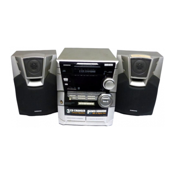
3 CD CHANGER
MINI MINI COMPONENT
MAX-N50/52/53/54/55/57
Manual
2. Exploded Views and Parts List
5. PCB Diagrams
CONTENTS
Advertisement
Table of Contents

Related Manuals for Samsung MAX-N55


Summarization of Contents
Alignment and Adjustments
1-1 Tuner
Alignment procedures for FM THD, FM Search Level, and AM(MW) I.F.
1-1-2 AM(MW),LW,SW1,SW2 Adjustment
Alignment procedures for AM, LW, SW1, and SW2 frequency bands.
1-2 Cassette Deck
Adjustments for tape speed, playback level, and REC bias voltage.
Electrical Parts List
MAXN50 Parts List
Comprehensive list of electrical components for the MAXN50 model.
Block Diagrams
4-1 MAIN Part(COMMON)
Block diagram illustrating the common main PCB circuit.
4-2 MAIN Part(Only MAX-N57)
Block diagram specific to the MAX-N57 main part.
4-3 CD Part(COMMON)
Block diagram for the common CD section.
Wiring Diagram
6. Wiring Diagram (COMMON)
Overall wiring diagram connecting various PCBs and components.
Schematic Diagrams
7-1 CD Parts(COMMON)
Schematic diagram for the common CD section.
7-2 MAIN Part (COMMON)
Schematic diagram for the common main PCB circuit.
7-3 MAIN Part (Only MAX-N57)
Schematic diagram specific to the MAX-N57 main part.
7-4 FRONT(COMMON)
Schematic diagram for the common front panel components.
7-5 TUNER(COMMON)
Schematic diagram for the common tuner section.
Need help?
Do you have a question about the MAX-N55 and is the answer not in the manual?
Questions and answers