
Related Manuals for Panasonic AKW92112


Summarization of Contents
Safety and Usage Precautions
About this product
General information about the Eco-POWER METER's purpose.
Installation environment
Conditions to avoid for proper operation and safety.
Installation
Guidelines for installing the Eco-POWER METER correctly.
As to measurement
Important considerations and limitations when taking measurements.
Static electricity
Precautions regarding static discharge during handling.
Cleaning
Recommended method for cleaning the unit.
Power supply
Instructions for safe and correct power supply connection.
Before power on
Key checks before powering on the unit for the first time.
Before change the setup
Advice on setting passwords and handling changes.
Chapter 1 Unit’s Outline
1.1 Measurement outline
Overview of the measurement capabilities and systems.
1.2 Measurement items
List of all measurable electrical parameters and their ranges.
1.3 Logging items
Details on recorded data and time stamps for logging.
Chapter 2 Parts Name and Working
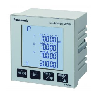
2.1 Parts Names
Identification and function of the unit's physical parts.
2.2 Key’s functions
Explanation of the purpose and operation of each key.
2.3 Indication on KW9M Eco-POWER METER
Guide to the display indicators and character representations.
Chapter 3 Wiring
3.1 Main unit terminal arrangement
Diagram and description of terminal block connections.
3.2 Wiring Diagrams
Visual guides for electrical connections of various systems.
3.3 How to attach the Current Transformer (CT)
Step-by-step instructions for correctly installing CTs.
3.4 For Input Connection
Details on connecting pulse inputs, including contact and non-contact types.
3.5 For Output Connection
Information on connecting PhotoMOS relay outputs.
3.6 RS485 Communication
Guidelines for setting up RS485 serial communication.
3.7 Backup Battery for Clock
Information on the backup battery for maintaining clock data.
3.8 Low Voltage Directive
Compliance requirements and conditions for Low Voltage Directive.
Chapter 4 Settings
4.1 Setting Flow
Overview of the sequence for parameter setup.
4.2 Password entry
Procedure for entering the password to access settings.
4.3 Password initialize
Steps to reset the password if forgotten.
4.4.1 Settings for power measurement
Configuration of parameters for power measurement.
4.4.2 Settings for demand measurement
Setup for various demand measurement types and intervals.
4.4.3 Settings for pulse measurement
Configuration for pulse input counting speed and clock correction.
4.4.4 Settings for communication
Parameters for RS485 communication setup.
4.4.5 Settings for optional functions
Customization of features like auto-off and display luminance.
4.4.6 Settings for time program
Configuration of time-based programs for different settings.
4.4.7 Settings for calendar timer
Setting the unit's internal date and time.
4.4.8 Password setting
How to set or change the access password.
4.4.9 Confirmation window
The process for confirming or cancelling setting changes.
Chapter 5 Various Functions
5.1 Pulse output function
Details on setting up pulse outputs for different events and conditions.
5.2 Counter function
Explanation of the counter operation modes and preset value changes.
5.3 Clock Correction Function
How to synchronize the unit's clock using pulse input.
5.4 Demand function
Selection and configuration of demand calculation methods.
5.4.4 Current Demand
Calculation method for current demand based on thermal meter principles.
5.4.5 Max. demand value
Information on recording maximum demand values over time.
5.4.6 Demand alarm output
How demand alarms are triggered and outputted.
5.4.7 Working at power failure and at recovery
Behavior of demand measurement during power interruptions.
Chapter 6 Display of each Value
6.1 Working of Monitor display
Overview of how to navigate between display modes.
6.2 Working of Monitor Display
Detailed display logic for various measurements.
6.2.1 Single-phase two-wire system
Display flow for single-phase two-wire measurements.
6.2.2 Single-phase three-wire system
Display flow for single-phase three-wire measurements.
6.2.3 Three-phase three-wire system
Display flow for three-phase three-wire measurements.
6.2.4 Three-phase four-wire system
Display flow for three-phase four-wire measurements.
6.2.5 Instantaneous power
How to view instantaneous power values for all phases/circuits.
6.2.6 Instantaneous power of each phase / each circuit
Displaying instantaneous power per phase or circuit.
6.2.7 Total integral power
Viewing total active, reactive, and apparent integral power.
6.2.8 Total integral export power
Viewing total active, reactive, and apparent integral export power.
6.2.9 Integral power of each phase / each circuit
Displaying integral power for individual phases/circuits.
6.2.10 Integral export power of each phase / each circuit
Displaying integral export power for individual phases/circuits.
6.2.11 Current
How to view current measurements for different phases.
6.2.12 Voltage
How to view voltage measurements for different phases.
6.2.13 Power factor
Display of the load's power factor.
6.2.14 Frequency
Display of the system frequency.
6.2.15 Current unbalance
Measurement of current imbalance between phases.
6.2.16 Voltage unbalancing
Measurement of voltage imbalance between phases.
6.2.17 Current THD
Display of Total Harmonic Distortion for current.
6.2.18 Voltage THD
Display of Total Harmonic Distortion for voltage.
6.2.19 Current n-order Harmonics
Viewing harmonic components of the current.
6.2.20 Voltage n-order Harmonics
Viewing harmonic components of the voltage.
6.2.21 Pulse Input Value
Display of values from pulse inputs.
6.2.22 Conversion value for integral active power
Display of conversion factors for integral active power.
6.2.23 Conversion value for integral export power
Display of conversion factors for integral export power.
6.2.24 Temperature
Display of the unit's internal temperature.
6.2.25 Calendar timer
Display of the current date and time.
6.3 Working of Logging Mode
How to access and view logged data.
6.3.1 Max. demand value
Viewing peak demand data logged monthly and by time-zone.
6.3.2 Max. / Min. value of electric power
Displaying logged maximum and minimum power values.
6.3.3 Integral power
Viewing logged integral power data by month and time-zone.
6.3.4 Max. /Min. value of each measured value
Displaying logged max/min values for various parameters.
6.4 Working of Demand Mode
How to view demand values based on the selected mode.
6.4.1 Peak Demand
Display of peak demand values.
6.4.2 Block Interval Demand (Sliding block、fixed block)
Viewing demand calculated over time intervals.
6.4.3 30-min. Demand
Display of 30-minute demand calculations and related values.
6.4.4 Current Demand
Display of current demand values.
Chapter 7 How to update the firmware
7.1 How to install USB driver
Instructions for installing the necessary USB driver for firmware updates.
7.2 How to update the firmware
Step-by-step guide for updating the unit's firmware.
Chapter 8 Specifications
8.1 Main unit
Electrical and environmental specifications for the main unit.
8.2 Input Specifications
Detailed electrical input specifications for voltage, current, etc.
8.3 Output Specifications
Specifications for the unit's output points, including pulse and alarm outputs.
8.4 Input Specifications
Detailed specifications for pulse and synchronized inputs.
8.5 Demand monitor and control specifications (common to 9, 10)
Specifications for demand monitoring and control functions.
8.6 Communication Specifications
Technical details for RS485 and USB communication.
8.7 Self-diagnostic function
Information on error codes and their meanings.
8.8 Power Failure Memory
How the unit retains data during power interruptions.
Chapter 9 Mounting
9.1 Dimensions
Physical dimensions of the main unit.
9.2 Panel mounting
Instructions and diagrams for mounting the unit in a control panel.
Need help?
Do you have a question about the AKW92112 and is the answer not in the manual?
Questions and answers