Table of Contents
Advertisement
Quick Links
Advertisement
Chapters
Table of Contents
Troubleshooting

Related Manuals for SolarEdge OP300-MV


Summarization of Contents
Disclaimers
Important Notice
Copyright and usage restrictions for the document.
Exclusion of Liability
Disclaimer regarding the accuracy and use of the document's content.
Handling and Safety Instructions
Safety Symbols
Explanation of safety symbols used throughout the document.
Instructions
Mandatory handling and safety instructions for installation and testing.
Support and Contact Information
Contact Details
Phone numbers and email for technical support and inquiries.
Chapter 1: Introducing the SolarEdge Power Harvesting System
What is the SolarEdge Power Harvesting Solution?
Overview of the SolarEdge power harvesting solution and its benefits.
SolarEdge Power Optimizer
Explanation of power optimizers for maximizing PV power output at module level.
Single Phase Inverter
Description of the inverter's function in converting DC to AC power and data transmission.
SolarEdge Monitoring Portal
Features of the portal for monitoring PV site technical and financial performance.
Installation Workflow
Overview of the steps for installing and setting up a new SolarEdge site.
Transport and Storage
Guidelines for safely transporting and storing the Single Phase Inverter.
Equipment List
Recommended tools and equipment for installing a SolarEdge system.
Chapter 2: Installing the Power Optimizers
Applicable Notes and Warnings
Important safety notes and warnings before installing power optimizers.
Step 1, Mounting the Power Optimizers
Procedures for securely mounting power optimizers to the racking.
Step 2, Connecting Each PV Module to a Power Optimizer
Instructions for connecting PV modules to specific power optimizer models.
Connecting Power Optimizers
Guidelines for connecting power optimizers to PV modules, including polarity checks.
Step 3, Connecting Power Optimizers in Strings
Steps for connecting power optimizers in series to form strings.
Verifying Proper Power Optimizer Connection
Methods to verify correct connection and voltage output of power optimizers.
Step 4, Recording Installation Information
Importance of recording serial numbers for troubleshooting and site layout.
Chapter 3: Installing the Inverter
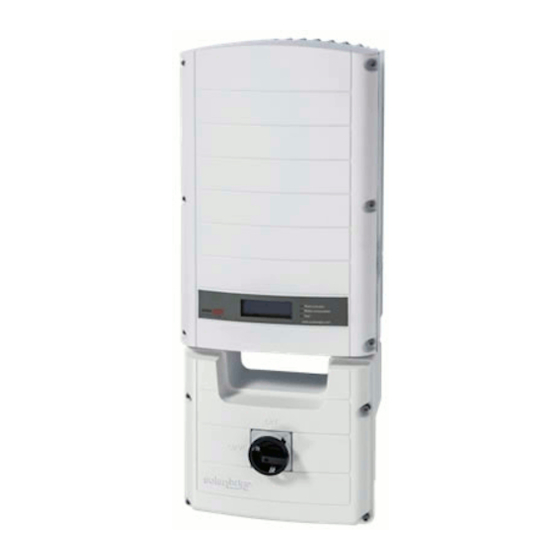
Identifying the Inverter
How to locate and identify the inverter's serial number and ratings.
Selecting the Mounting Location
Considerations for choosing a suitable mounting location for the inverter.
Chassis Clearance
Required clearance around the inverter for heat dissipation.
Mounting the Inverter
Step-by-step instructions for physically mounting the inverter.
Connecting the Inverter
Overview of inverter connection procedures and configuration.
AC Grids Supported
Diagrams illustrating AC grid configurations supported by the inverter.
Connecting the Single Phase Inverter
Detailed guidance on connecting the inverter's power and communication cables.
Installing the AC/DC Safety Switch
What is the AC/DC Safety Switch?
Explanation of the AC/DC Safety Switch and its function.
AC/DC Safety Switch Package Contents
List of items included in the AC/DC Safety Switch package.
Mounting the Switch
Steps for mounting the AC/DC Safety Switch to the inverter bracket.
Connecting the Switch to the Inverter
Instructions for connecting AC and DC wires from the switch to the inverter.
Opening the Switch Cover
Procedure for opening the AC/DC Safety Switch cover for wiring.
Connecting the AC
How to connect AC wires to the AC/DC Safety Switch terminal block.
Connecting the DC
How to connect DC wires to the AC/DC Safety Switch terminal block.
Closing the AC/DC Safety Switch Covers
Steps for closing and securing the AC/DC Safety Switch covers.
AC/DC Safety Switch Technical Specifications
Technical specifications for the AC/DC Safety Switch models.
Ground Fault Circuit Interrupter
GFCI Requirements and Configuration
Information on internal and external GFCI requirements and settings.
Chapter 4: Commissioning the Installation
Commissioning – Workflow
Steps for activating, commissioning, and verifying the system's operation.
Step 1, Activating the System
Initial activation stages of the SolarEdge system.
Step 2, Pairing Power Optimizers to the Inverter
Process of logically pairing power optimizers with their inverter.
Step 3, Verifying Proper Operation
Procedures to verify the inverter's steady operation and indicators.
Step 4, Reporting and Monitoring Installation Data
How to register and access site information via the SolarEdge Monitoring Portal.
Chapter 5: Replacing and Adding System Components
Modifying an Existing Installation
Procedures for altering an existing SolarEdge installation.
Moving Power Optimizers Between Inverters
Steps to transfer power optimizers between inverters within the same site.
Chapter 6: Setting Up Communication
Communication Dataflow
How site information is transferred from SolarEdge to the Monitoring Portal.
Connector Panel Overview
Identification of connectors and glands on the inverter.
Communication Types
Overview of available communication methods (RS232, Ethernet, RS485).
Creating an RS232 (UART) Connection
Steps for establishing an RS232 connection for modem communication.
Creating an Ethernet (LAN) Connection
Instructions for connecting the inverter to a LAN via Ethernet.
Creating an RS485 Bus Connection
Procedure for creating an RS485 bus for connecting multiple inverters.
Verifying the Connection
Steps to confirm successful communication setup with the SolarEdge server.
Troubleshooting Communication
Common communication issues and their solutions.
Chapter 7: Inverter User Interface
Inverter LCD Panel and LEDs
Description of the inverter's LCD panel and LED indicators.
Inverter LCD Panel and User Buttons
Usage of the LCD panel and buttons for inverter status and configuration.
Initial Inverter Status Window
Details of the initial status window displayed on the inverter's LCD.
Main Inverter Status Window
Overview of the most informative status window for power, voltage, and temperature.
Energy Meter Window
Display of total energy produced by the inverter over time.
Telemetry Window
Display of telemetry data from power optimizers to the inverter.
ID Status Window
Information on software version and country configuration of the inverter.
Communication Status Window
Display of current communication settings and status.
IP Status Window
Details of the Ethernet configuration for the inverter.
Configuring the Inverter Using the LCD Panel and User Buttons
Basic inverter configurations using the LCD panel and buttons.
LCD Button Menu Options
Accessing setup and logs via the LCD button without opening the inverter.
Configuring the Inverter Using the SolarEdge Configuration Tool
Using the software tool for advanced inverter configuration and firmware updates.
Appendix A: Errors and Troubleshooting
About This Appendix
Introduction to the appendix listing inverter error messages and troubleshooting.
Appendix B: Technical Specifications
About This Appendix
Overview of the appendix containing technical specifications of system components.
Single Phase Inverter Specifications
Detailed technical specifications for SolarEdge single-phase inverters.
Appendix C: Power Optimizer Mechanical Specifications
About This Appendix
Introduction to mechanical specifications of SolarEdge power optimizers.
OP250-LV, OP300-MV, OP400-MV Power Optimizers
Mechanical specifications for specific SolarEdge power optimizer models.
PB250-AOB and PB350-AOB Power Optimizers
Mechanical specifications for PB250-AOB and PB350-AOB power optimizers.
Appendix D: Inverters Power De-rating
Inverter Power De-rating Graph
Graph showing inverter output current reduction based on ambient temperature.
Appendix E: Limited Product Warranty
Warranty Coverage and Claims
Details on warranty periods, coverage, and how to submit a claim.
Need help?
Do you have a question about the OP300-MV and is the answer not in the manual?
Questions and answers