Table of Contents
Advertisement
Quick Links
T T e e c c h h n n i i c c a a l l
S S e e r r v v i i c c e e M M a a n n u u a a l l
3 3
3 3
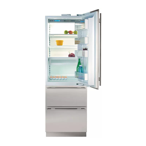
I I n n t t e e g g r r a a t t e e d d
S S e e r r i i e e s s
I I n n t t e e g g r r a a t t e e d d
S S e e r r i i e e s s
( ( 7 7 0 0 0 0 - -
T T A A L L L L ) )
( ( 7 7 0 0 0 0 - -
T T A A L L L L ) )
© SUB-ZERO FREEZER COMPANY INC.
2006 ALL RIGHTS RESERVED
JOB AID #3758412
(Revision B - December 2006)
Advertisement
Chapters
Table of Contents
Troubleshooting

Summarization of Contents
General Information
Introduction
Overview of the technical service manual's purpose for 700-3 Series Tall units.
Important Safety Information
Details product safety labels, signal words (WARNING, CAUTION), and notes.
Warranty Information
Summary of the 2, 5, and 12 year residential warranties and special warranties.
Model Descriptions
Brief descriptions of the 700-3 Tall Unit models covered in the manual.
Installation Information
Installation Considerations
Common installation issues and potential customer complaints.
Unit Leveling
Instructions on how to level the unit using front and rear leveling legs.
Door and Drawer Adjustment
Information on adjusting door and drawer panels, noting unit must be level.
Dual Unit Installations
Requirements for dual unit heater packages for side-by-side installations.
Electronic Control System Information
Electronic Control Terminology & Component Descriptions
Definitions of terms and components related to the electronic control system.
Basic Electronic Control System
Overview and schematic of the basic 700 Series electronic control system.
Control Board Layout and Summary Table
Diagram and table showing control board connection points and functions.
Basic Electronic Control Input Operations
Explains basic operations like Unit ON/OFF, set-point adjustment, and ice maker control.
Troubleshooting Input Operations
Explains diagnostic mode, manual component activation, and temperature log recall.
Sealed System Information
HFC-134a Refrigerant Service Information
General rules and procedures for servicing systems containing HFC-134a refrigerant.
Sealed System Repair Procedures
Troubleshooting steps for common sealed system problems like leaks or contamination.
Sealed System Operation
Explains the basic sealed system components and refrigerant flow.
Air Flow & Fan Blade Spacing
700TC/I-3 and 736TC/I-3 Air Flow and Fan Blade Spacing
Diagrams and specifications for airflow and fan blade spacing for specific models.
700TR-3 and 736TR-3 Air Flow and Fan Blade Spacing
Diagrams and specifications for airflow and fan blade spacing for specific models.
Icemaker Information
Icemaker System Information
Overview of icemaker models used and additional system information.
Modular Icemaker Operation (700TFI-3 Only)
Explains how the modular icemaker operates and its electrical schematic.
Modular Icemaker Test Procedures (700TFI-3 ONLY)
Step-by-step voltage and continuity tests for the modular icemaker.
Component Access/Removal
Component Access and Removal
General guidance on accessing and removing components, including warnings and cautions.
Exterior Cosmetic and Mechanical Components
Procedures for removing exterior parts like kickplates, side molding, and switches.
Interior Cosmetic, Mechanical and Electrical Components
Procedures for accessing and removing internal components like shelves and diffusers.
Compressor Removal
Detailed procedure for removing the compressor, including electrical and tubing disconnections.
Sealed System Components
Procedures for removing sealed system components like evaporators and filter-driers.
Troubleshooting Guides
How to Use the Error Code Troubleshooting Guide
Guide on how to use error codes for diagnosing unit malfunctions.
Error Code Troubleshooting Guide
Detailed troubleshooting actions for specific error codes.
How to Use General Troubleshooting Guide
Instructions on how to use the general troubleshooting guide to diagnose problems.
Sealed System Troubleshooting / Diagnostic Tables
Tables for diagnosing sealed system issues based on pressures.
Technical Data
Model 700TC/I-3
Technical specifications for the 700TC/I-3 model.
Model 700TR-3
Technical specifications for the 700TR-3 model.
Model 700TF/I-3
Technical specifications for the 700TF/I-3 model.
Wiring Diagrams/Schematics
Wiring Diagram Model: 700TC-3
Wiring diagram for the 700TC-3 model, showing component connections.
Wiring Schematic Model: 700TC-3
Wiring schematic for the 700TC-3 model, detailing electrical paths.
Wiring Diagram Model: 700TR-3
Wiring diagram for the 700TR-3 model, showing component connections.
Wiring Schematic Model: 700TR-3
Wiring schematic for the 700TR-3 model, detailing electrical paths.
Wiring Diagram Model: 700 TF/I-3
Wiring diagram for the 700 TF/I-3 model, showing component connections.
Wiring Schematic Model: 700 TF/I-3
Wiring schematic for the 700 TF/I-3 model, detailing electrical paths.
Wiring Diagram Model: 736TC/I-3
Wiring diagram for the 736TC/I-3 model, showing component connections.
Wiring Schematic Model: 736TC/I-3
Wiring schematic for the 736TC/I-3 model, detailing electrical paths.
Wiring Diagram Model: 736TR-3
Wiring diagram for the 736TR-3 model, showing component connections.
Wiring Schematic Model: 736TR-3
Wiring schematic for the 736TR-3 model, detailing electrical paths.


Need help?
Do you have a question about the 736TCI-3 and is the answer not in the manual?
Questions and answers