Table of Contents
Advertisement
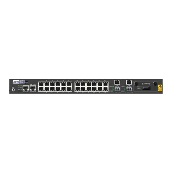
ZXR10 3900A/3200A Series
Intelligent Routing Switch
Hardware Installation Manual
Version 2.8.23.A
ZTE CORPORATION
ZTE Plaza, Keji Road South,
Hi-Tech Industrial Park,
Nanshan District, Shenzhen,
P. R. China
518057
Tel: (86) 755 26771900
Fax: (86) 755 26770801
URL: http://ensupport.zte.com.cn
E-mail: support@zte.com.cn
Advertisement
Table of Contents

Related Manuals for Zte ZXR10 3252A


Summarization of Contents
Chapter 1 Safety Introduction
Safety Introduction
Provides instructions for safe operation, emphasizing qualified professionals and adherence to local safety codes.
Safety Descriptions
Defines safety symbols and explains special attention items for ZXR10 3900A/3200A configuration.
Chapter 2 System Overview
Product Overview
Introduces ZXR10 3900A/3200A series products, their applications, and features like PoE and QoS support.
Functions
Details the extensive functions of ZXR10 switches, including Layer 2, routing protocols, ACL, and QoS capabilities.
Technical Features and Parameters
Lists detailed technical specifications, dimensions, weight, power, and memory for various ZXR10 models.
Chapter 3 Structure and Principle
Working Principles
Explains the modular design and operational principles of ZXR10 3900A/3200A series Ethernet switches.
Hardware Structure
Details the physical structure, chassis, front and back panels of various ZXR10 models.
Chapter 4 Units/Components Description
Control and Switching Board
Describes the core control and switching board, its interfaces (Console, Management), and Ethernet connectivity.
Line Interface Card
Details various Line Interface Cards like FGEI, FGFI, FGFE, FBFE, their interfaces, and indicators.
Chapter 5 Power Module
Power Module Overview
Provides an overview of the built-in active power supply and its support for DC and AC power inputs across models.
Active Power Supply
Describes the active power supply input interfaces, supporting 48V DC and 220V AC power for ZXR10 3900A/3200A.
Standby Power Supply
Details the 12V standby DC power supply input supported by specific ZXR10 models.
Chapter 6 Installation and Debugging
Equipment Installation
Covers methods for installing ZXR10 switches, including desktop and 19-inch cabinet mounting procedures.
Cable Installation
Explains the installation of power, console, network, and fiber optic cables for ZXR10 devices.
Power-on Procedure
Outlines the steps for safely powering on the ZXR10 RPS180, including pre-checks and sequential power activation.
Chapter 7 RPS180 Backup Power
System Overview
Introduces the ZXR10 RPS180 as a redundant power enhancement providing standby 12V power.
Functions
Details the input capabilities (AC/DC) and output (12V) of the RPS180, and its compatibility with ZTE switches.
Technical Features and Parameters
Lists technical specifications for RPS180, including dimensions, weight, power, and environmental requirements.
Structure and Principle
Explains the working principles of RPS180 AC and DC models, detailing internal cards like CAPU, CDPU, and LPDB.
Hardware Structure
Describes the physical structure of the RPS180, including its 1U height, 19-inch box design, and internal cards.
Boards
Details the function of key boards within the RPS180, such as the Power Conversion Board, CAPU, CDPU, and LPDB.
Need help?
Do you have a question about the ZXR10 3252A and is the answer not in the manual?
Questions and answers