Advertisement
Instruction Manual
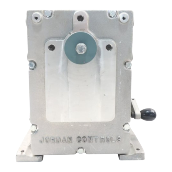
SM-1700 Series Rotary Actuator
Due to wide variations in the terminal numbering
Table of Contents
General Information .............................................. 2-3
Introduction ....................................................... 2
Cautions ............................................................. 2
Receiving/Inspection .......................................... 2
Storage ............................................................... 2
Equipment Return .............................................. 2
Identification Label............................................. 3
Abbreviations Used in This Manual .................... 3
General Actuator Description ............................. 3
Basic Models ...................................................... 3
Specifications ........................................................ 4-5
Actuator ............................................................. 4
Options .............................................................. 5
Installation ............................................................. 5-6
Typical Wiring Diagrams ........................................ 7-8
Start Up .............................................................. 9-11
Troubleshooting ................................................. 12-13
Parts Identification ............................................. 14-16
Parts List ............................................................ 17-18
Maintenance ..................................................... 19-20
Major Dimensions ............................................. 21-22
Linkage Options ..................................................... 21
Actuator ................................................................. 22
of actuator products, actual wiring of this device
should follow the print supplied with the unit.
1
Advertisement
Table of Contents

Related Manuals for JORDAN CONTROLS SM-1730


Summary of Contents for JORDAN CONTROLS SM-1730
- Page 1 Instruction Manual SM-1700 Series Rotary Actuator Table of Contents General Information ..........2-3 Introduction ............2 Cautions ............. 2 Receiving/Inspection .......... 2 Storage ............... 2 Equipment Return ..........2 Identification Label..........3 Abbreviations Used in This Manual ....3 General Actuator Description ......3 Basic Models ............
- Page 2 Report all damage immedi- ately to the freight carrier and Jordan Controls, Inc. If any of the instructions are not understood, contact your Jordan Controls representative for clarification.
-
Page 3: Identification Label
The SM-1700/AD-8130 series feature an integral servo is a three phase ac, reversible model comp- amplifier. These models require 120 or 240 Vac atible with Jordan Controls remotely located AD-8900 series (depending on model) unswitched, single phase line servo amplifier or any bi-directional contact type control. - Page 4 Input Pow er Current (Amps) Model Volts/PH/Hz Stall *Time/Torque **Model sec./in. lbs. (Nm ) 240/3/50-60 SM-1715* 380/3/50 SM-1715 12/1200 (136), 24/1200 (136), 48/1200 (136) 480/3/50-60 0.65 SM-1720 60/1800 (203), 31/1800 (203) SM-1720 120/1/50-60 60/2400 (271) SM-1790 SM-1730 120/1/50-60 SM-1740 24 Vdc...
-
Page 5: Actuator
AC powered actuators or remote model AD-7530 for SM-1740 DC powered actuators or : 20 tooth splined shaft for use with remote model AD-8900 for SM-1715 three phase splined drive arm. actuators. Also model AD-8230/EC-10B36 for remote mounted single phase AC powered actuators. - Page 6 Typical wiring diagrams are shown on pages 7-8. Jordan Controls has designed a three piece “wedge- lock” coupling which can be adjusted to align the driven device to the actuator output shaft with no The wiring diagram shows the fundamental connec-...
-
Page 7: Options
AC Power Applied to Terminals DC Power Applied to Terminals Actuator Action 1 & 2 1 & 3 1(+) & 2(-) 1(-) & 2(+) Viewing Output Shaft 1. The torque limit switches are factory set to trip if the rating of the actuator is exceeded. 2. - Page 8 1. All references to actuator output shaft rotation are as viewed facing the actuator output shaft. 2. An increasing command signal will result in CW rotation of the actuator output shaft. 3. The torque limit switches are factory set to trip if the torque exceeds the actuator rating. Do not adjust these trip points.
- Page 9 5. Apply motor power to drive the actuator to the desired CCW position or until PL2 trips and stops the motor. If the driven device is not at the desired position: a. Remove motor power. NOTE: The actuator is shipped in its mid-travel position. b.
-
Page 10: Installation
For the unit to function optimally, the 4mA end of the feedback potentiometer must be preset to 50 ohms. 1. Position the actuator to the desired 4mA setting. 2. With potentiometer resistance at 50 ohms, adjust ELEVATION for 4.0mA output. 3. - Page 11 2.In equation, if the value of X is equal to 0.5 or 2, and if Figure 2 upper shaft position is not equal to 100% (90°), and/or lower shaft position is not equal to 5% (0°). To lay out the cam shape for the desired input-output relationship, it is necessary to determine outputs (rise in cam), for various inputs (amount of cam rotation).
- Page 12 TROUBLE POSSIBLE CAUSE REMEDY a. No power to actuator a. Check source, fuses, wiring b. Let motor cool and determine why b. Motor overheated and internal overheating occurred (such as, thermal switch tripped (single phase excessive duty cycle or ambient AC motors only) temperature) c.
- Page 13 a. Power not applied for other a. Correct power problem direction b. Power always applied to one direction and electrically stalls when b. Correct power problem applied for opposite direction c. Open limit switch for other c. Adjust or replace limit switch as Motor runs, but only one way direction required...
-
Page 14: Parts Identification
Letters in balloons refer to gear assembly drawing on page 15. Numbers in balloons refer to parts identification list on pages 17-18. - Page 15 Numbers in balloons refer to parts identification list on pages 17-18.
- Page 16 Numbers in balloons refer to parts identification list on pages 17-18.
- Page 17 Recommended Spare Parts Indicated in Bold DESCRIPTION PART NUMBER Worm Gear 16A-015673-001 Gasket, Gear Cover 13C-016024-001 Bushing 18B-SP1988-066 Capacitor 5 MFD (1710) 24B-029812-005 Gasket, Rear Cover 13C-015754-001 Bushing (2nd Stage) 18B-SP1988-067 Capacitor 10 MFD (1720) 24B-029812-008 Bushing (3rd Stage) 18B-SP1988-007 Capacitor 10 MFD (1730) 24B-029812-007 Bushing (4th Stage)
- Page 18 (Item 11) Part # (Item 14) Part # (Item 15) 61B-026406-004 16B-015633-001 65B-016034-001 SM-1710 61B-026406-004 16B-015633-003 65B-016034-003 61B-026407-001 16B-003806-015 65B-016034-005 23C-038332-001 16B-015633-001 65B-016034-001 SM-1715 23C-038332-001 16B-015633-003 65B-016034-003 23C-038333-001 16B-003806-015 65B-016034-005 61B-026406-003 16B-015633-004 65B-016034-008 SM-1720 SM-1790 61B-026407-002 16B-017896-001 65B-016034-007 61B-026406-003 16B-015633-001...
-
Page 19: Maintenance
Under normal service conditions the motor, gearing, bearings, and parts are all pre-lubricated and should The torque limit switches are factory set and field not require periodic maintenance. If for any reason the adjustment is not advised unless proper test equip- unit is disassembled in the field, all oilite bushings ment is available. -
Page 20: Actuator
1. Disconnect all power to the actuator. 2. Remove screws, washers and rear cover. 1. Disconnect all power to the actuator. 3. Disconnect actuator output shaft from driven 2. Remove screws, washers, and rear cover. device and remove actuator from mount. 3. - Page 21 1. Maximum total link length is specified to prevent buckling under compressive load. 2. Adjustable drive arms are also available to allow length to vary from 6 to 10 inches (152 to 254 mm). In this case, the adapter-clevis has rod ball ends with lubrication fittings.
- Page 22 2. The SM-1700 series actuators can be foot, face or side mounted. 3. Overall depth is approximately 13 inches (330 mm) on the SM-1715 three phase model. 4. The output shaft is available in a one inch (25.4 mm) diameter with 1/4 inch (6.35 mm) square keyway, or with...
- Page 24 The dimensions in this manual are subject to change without notice and should not be used for preparation of drawings or fabrication of installation mounting. Current installation dimension drawings are available upon request. JORDAN CONTROLS, INC. 5607 West Douglas Avenue Milwaukee, Wisconsin 53218...
Need help?
Do you have a question about the SM-1730 and is the answer not in the manual?
Questions and answers